Categorías
Etiquetas
AYUDATECNICOS.COM
Informacion para Tecnicos de Sistemas y Microinformatica
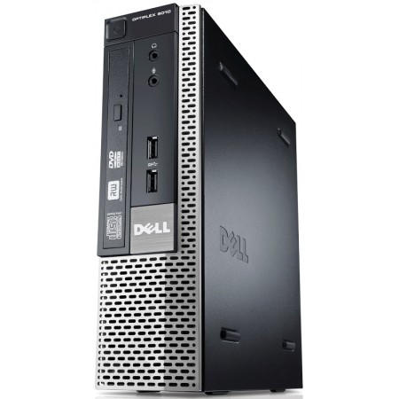
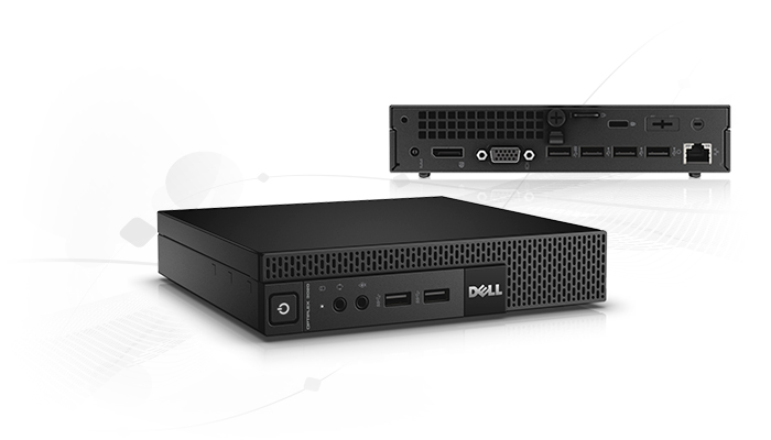
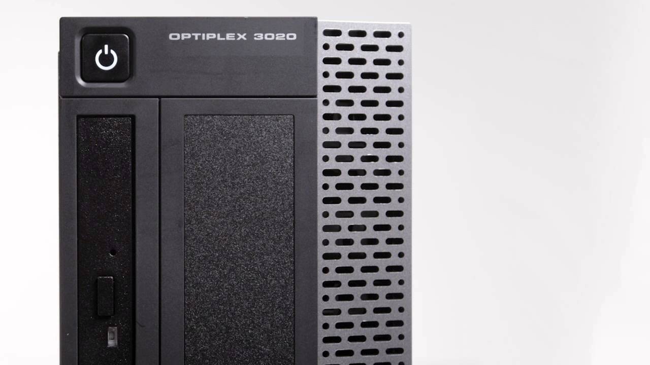
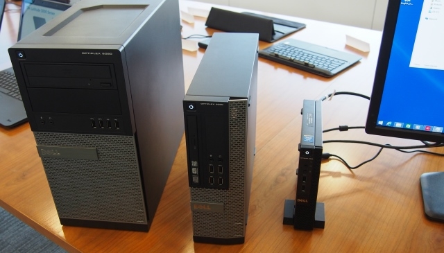
Problemas de Inicio Dell Optiplex 3020
Los Modelos Dell Optiplex series 3020 son equipos muy productivos en ambito empresarial como domestico.
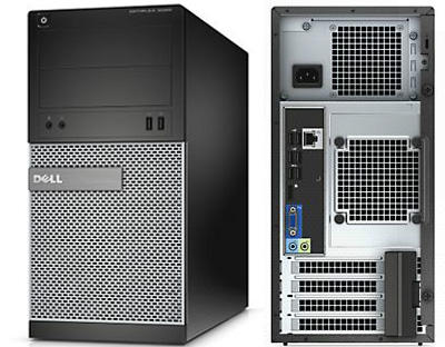
En las ultimas instalaciones he podido observar, algun problema de inicio con estos modelos. Al arrancar estos sistemas como todos realiza un POST (Power On Self Test ), si hay algun problema lo refleja en pantalla, durante el POST el led de encendido permanece en color Ambar, al comprobar que esta todo correcto el led de encendido se pone en blanco.
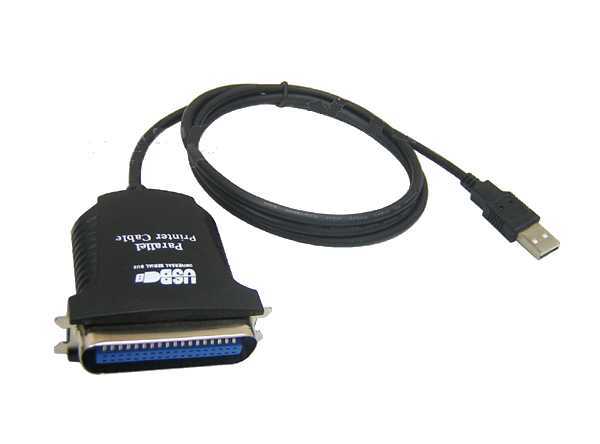
Cuando utilizamos algun tipo de impresoras sin soporte para conexiones USB, como la antigua gama de Impresoras Epson, Canon, Oki, etc…
.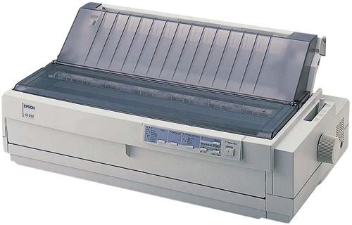
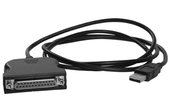
tenemos que utilizar conversores tipo USB a Centronics o USB a Paralelo 25 Pins.
El problema observado es que al intentar arrancar el equipo, no llega a ponerse el led de arranque en blanco, se queda en ambar y no arranca el equipo. Lo normal es que volvamos a pulsar el boton repetidas veces y entremos en un ciclo que el equipo se queda sin dar ningun tipo de respuesta.
Solucion:
1º Sacaremos el cable de alimentacion dela Fuente de Alimentacion durante 20 segundos, volveriamos a conectarlo a la Fuente de Alimentacion.
2º Los mas Importante nos aseguraremos ahora y en los arranque sucesivos que la Impresora que tenemos conectada con el conversor Usb a Paralelo este apagada, la encenderemos cuando el sistema haya arrancado.
Supongo que la razon es que el sistema antes de arrancar considera que hay algun tipo de incompatibilidad electrica en el puerto Usb y no arranca. Probando con las opciones de Prioridad de dispositivos del Set-Up, no hay cambios con este problema si situamos el Disco Duro, el DVD o dispositivos externos Usb con otro orden de prioridad en el arranque.
Si tenemos en cuenta encenderlo con la Impresora apagada, esta serie de DELL es una eleccion muy interesante para cualquier necesidad.
Posted in Hardware
Problemas Instalando un Service Pack en Windows XP, Vista,7
Cuando instalamos un Service Pack en Windows XP, si los recursos de la maquina son muy justos, o es un equipo que anteriormente ha tenido algun problema de Virus, nos tardara mucho tiempo y dudaremos si realmente esta actualizando o se nos ha quedado bloqueado.
Normalmente suele ser en el ultimo paso de la actualizacion.

La mejor opcion es ir a el Visor de Sucesos para estar seguros que esta todo funcionando bien.
Boton derecho sobre Mi PC – Administrar – Visor de Sucesos – Sistema, si estamos sobre Windows Xp
Boton derecho sobre Equipo – Administrar – Administracion de equipos- Visor de eventos – Registros de Windows – Sistema , si estamos sobre Windows 7

Nos ira indicando cuando empieza a instalar cada parche o HotFix en el sistema.
Si pinchamos en cada uno de ellos:

Nos dira cual es el KBXXXXXX que se ha instalado y si ha sido satisfactorio.
Al finalizar la actualizacion del Service Pack nos saldra un mensaje como este, de fin de paquete.

Al reiniciar el sistema si la instalacion ha terminado correctamente y al instalador ya ha terminado su tarea, saldra un sucesos parecido al siguiente, indicando que el servicio de actualizacion del Service Pack ha concluido.

Iremos al sistema ( boton derecho Mi PC – Propiedades – General , desde Windows Xp o Boton derecho – Equipo – Propiedades , desde Windos 7 ) para asegurarnos que la informacion que da de el sistema es la que queriamos.


Posted in Sistemas Operativos
Actualizar Memoria en un Passport 8600
This document describes how to install a memory upgrade to the following Passport CPU modules:
• 8190SM
• 8690SF
• 8691SF
With the Passport 8000 Switch Series Software Release 3.5 and above you must upgrade the 8190SM and the
8690SF to 256MB.
Although it is not required with Release 3.5, Nortel Networks recommends that you upgrade the 8691SF to
256MB to accommodate future capabilities. The 256MB memory upgrade kit (Order No. DS1411016)
contains the following:
• 256 MB dual inline memory module (DIMM).
• 256 MB label to apply to the faceplate of the CPU module
• 3 CPU part number labels See Table 1 to identify the appropriate label to apply to your CPU module pan.
Note: Nortel Networks only supports the 256 DIMM contained in this memory upgrade kit (Order No.
DS1411016). Installing a 256MB DIMM other than the one enclosed in this memory upgrade kit will void any
warranty or maintenance contract on the module.
Handling DIMMs and Passport 8600 Modules
The 8000 Series modules are sensitive to static electricity. Static discharge from your clothing or other fixtures
around you, even at levels that do not create a spark, can cause damage.
To prevent static discharge damage when you work with 8000 Series modules, place each module on a
grounded antistatic mat until you are ready to install or leave it in the sealed ESD bag.
Wear a discharge leash or wrist strap to free yourself of static before you touch a module.
To upgrade your Passport CPU memory upgrade you must first remove the Passport CPU Module from the
Passport 8000 Series chassis.
Removing the Passport CPU Module
To install your Passport CPU memory upgrade you must first remove the Passport CPU Module from the
Passport 8000 Series chassis.
If you have one Passport CPU Module installed in your chassis,
you must power down your switch. If you have two Passport CPU Modules you can remove the Passport CPU
module with the power on or off.
Refer to instructions for turning power off in your chassis installation manual. Refer to Installing 8600 Modules
and use the instructions for removing a module.
Be sure to place the Passport CPU Module on a clean, nonconductive surface.
Removing the DIMM from the Passport CPU Module To upgrade the Passport CPU Module, you must first
remove the installed DIMM.
To remove the DIMM from the Passport CPU Module:
1 Locate the DIMM to remove (Figure 1).
Figure 1 Location of DIMM on the Passport CPU Module

2 Pull the locking tabs on each side of the DIMM outward to unseat the DIMM (Figure 2).

3 Grasp the top corners of the DIMM and pull it out and away from the connector.
Installing the Memory Upgrade DIMM
This procedure assumes you have already removed the DIMM from the appropriate socket as described in the
previous section.
Your upgrade kit contains one 256 MB DIMM. To install it:
1 Remove the DIMM from the package and place it on a static-free surface.
2 Holding the DIMM by its top corners (opposite the connector edge), orient the DIMM so that the notches align
with the keys in the DIMM socket (Figure 3).

3 Insert the DIMM into the Passport CPU connector socket and press it in to seat the DIMM firmly in the socket(Figure 4).

4 Press the locking tabs in one at a time to secure the DIMM in its locked position (Figure 5).
Caution: Although it is normal to feel a slight resistance as the DIMM comes to its locked position, be careful not
to use too much force. You may damage the DIMM socket by forcing the DIMM into the locked position.

Attaching the labels
One 256MB label and 3 CPU part number labels are contained in your memory upgrade kit.
If you need to return your module to Nortel Networks, to ensure rompt servicing please follow these steps to
attach the labels:
1 Remove the paper backing from the 256MB label.
2 Attach the 256 MB label to the CPU module faceplate next to the module model number as shown in Figure 6.

3 Locate the appropriate part number label for your CPU (Table 1).
Table 1
Table 1 Choosing the appropriate CPU module part number label

4 Remove the paper backing from the appropriate CPU part number label.
5 Attach the appropriate CPU part number label to the bottom of the CPU module as shown in Figure 7.
Figure 7 Location of CPU part number label on the bottom of the CPU module

5 Install the Passport CPU Module in the chassis. To install the Passport CPU module, refer to Installing 8600
Modules and follow the instructions for installing a module
Connecting to Nortel Networks online
This section describes products, services, and support systems that can be accessed online.
Hard-copy technical manuals
You can print selected technical manuals and release notes free, directly from the Internet. Go to the
www.nortelnetworks.com/ documentation URL. Find the product for which you need documentation. Then locate
the specific category and model or version for your hardware or software product. Use Adobe* Acrobat Reader*
to open the manuals and release notes, search for the sections you need, and print them on most standard
printers. Go to Adobe Systems at the www.adobe.com URL to download a free copy of the Adobe Acrobat
Reader
How to get help
If you purchased a service contract for your Nortel Networks product from a distributor or authorized reseller,
contact the technical support staff for that distributor or reseller for assistance.
If you purchased a Nortel Networks service program, contact Nortel Networks Technical Support. To obtain
contact information online, go to the www.nortelnetworks.com/cgi-bin/comments/comments.cgi URL, then click
on Technical Support.
From the Technical Support page, you can open a Customer Service Request online or find the telephon
number for the nearest Technical Solutions Center.
If you are not connected to the Internet, you can call 1-800-4NORTEL (1-800-466-7835) to learn the telephone
number for the nearest Technical Solutions Center. An Express Routing Code (ERC) is available for many Nortel
Networks products and services. When you use an ERC, your call is routed to a technical support person who
specializes in supporting that product or service. To locate an ERC for your product or service, go to the
http://www.nortelnetworks.com/help/contact/erc/index.html URL.
Posted in Hardware, Nas & San, Networking, Redes
Instalacion De Un Fujitsu FibreCat N40i
Preface
FibreCAT N40i with Windows Storage Server 2003 is an optimized file server based on Microsoft Windows
technology that is designed for high reliability, availability, and ease of management.

The base for this system is Microsoft Windows Server 2003 ‘ Standard Edition operating system with
additionally installed Server Appliance Kit (SAK) 3.0. SAK allows complete administration of almost the
whole system using Internet Explorer.
Supported network protocols are
· CIFS
· NFS
· HTTP
· Apple Talk
· NCP (with SfN)
· iSCSI
The intention of this readme is to help owners of the FibreCAT N40i to be successful in installation and
administration. It describes the main steps to do the job, but does not detail any system features, neither
for the hardware nor the underlying Microsoft Windows operating system. To get more information
refer to the documentation mentioned at the end of this readme
The system is factory preinstalled and ready to use. If the system is just powered on without doing
anything else, it will start and configure itself with default parameters. That means, the system
gets a default name, sets the password to fibrecat, configures both onboard Ethernet ports to assign
IP addresses from a DHCP pool, and joins itself to workgroup WORKGROUP. If you don t like
these settings, continue reading paragraph Setting Configuration Parameters.
Do not power on without prepared configuration media if you do not want default settings.
System Configuration
Because the FibreCAT N40i is factory preinstalled, it can be put into operation just after unpacking. If
the system is just powered on, it will get a default configuration as described in paragraph Preface.
Supposed, a system configuration with customized settings is preferred, there must be a file
sysprep.inf supplied during system configuration phase. This is done by plugging in an USB device
(Floppy or Memory Stick) to an USB port, which contains the configuration data.
How this will be accomplished is described in paragraph Setting Configuration Parameters.
The time required for setting up a preinstalled FibreCAT N40i will be around 10 minutes for configuration
and 2 reboots, the initial boot after power on and the final boot.
New Installation
On delivery the FibreCAT N40i is factory preinstalled.
If for some circumstance it may be necessary to install the system again from scratch, you have to
install and configure the operating system by yourself using the provided DVD.
To perform a complete (re)installation do the following steps:
1. Put the DVD into the corresponding drive and power on the system.
If customized system configuration is required, prepare prior powering on the system an USB
device which holds a file sysprep.inf as described in paragraph: Setting Configuration Parameters.
2. Wait for round about 15 minutes when the system copies data from the DVD to the disks and
calculates checksums of all copied data.
3. The system automatically reboots and performs the final configuration, which will last additional
10 minutes. During this step either
a.) the default configuration will be done, or
b.) if the file sysprep.inf is present on an USB device the customized configuration will be performed.
After finishing these three steps, administration can be done over LAN using the Internet Explorer.
All above mentioned steps are explained here in detail.
For further reading see paragraph FibreCAT Deployment / Re-Installation and Appendix A
Setting Configuration Parameters (optional)
There is the possibility to configure the FibreCAT N40i with customized configuration data. Therefore
an USB device (Floppy or Memory Stick) must be supplied which contains a file sysprep.inf with the
configuration data. Here will be described how to create the sysprep.inf file.
Insert the DVD into a Microsoft Windows system (PC) and wait for starting the DVD automatically. This
will first open a command window showing some additional instructions and afterwards it will start the
configuration tool CfgEdit.exe. CfgEdit will guide through all necessary steps to create a functional
sysprep.inf file.
Important: Carefully choose the configuration parameters you enter. Wrong input might leave the
system in non-operable state during the setup later!
The following screenshots of CfgEdit.exe will show you which parameters you®ll have to enter.
Welcome screen of CfgEdit.exe:

Following the “Next® button you are prompted to specify whether you want to create a new configuration
file (answer file) or if you want to change an existing one:

Browse at this point to the drive letter of the DVD on the system used. There is a default file
sysprep.inf in the directory ”Deploy–which should be used as base for further editing.
Next the default user name and organization have to be entered:

Next step is to define computer name and the administrator password:

Remember computer name and password!
You®ll need these values to be able to log in to your FibreCAT N40i later.
Take care of your password! It will appear as clear text in the configuration file. So you should later
change the password when the system runs.
Next network configuration has to be done:

Here you can select only two network adapters. The network interfaces mentioned here are the two
Gigabit ports which reside on the system board. If there are additional adapters in the system, you
must configure them later when the FibreCAT N40i runs. It can be done using the Web-GUI or remote
console.
In the next steps you will be guided through the network configuration for both ports. If no actions are
taken, i.e. the default settings are used, the system tries to configure DHCP network addresses. It®s
possible to use static and/or dynamic addresses on different ports.
After port 1 is finished port 2 will follow.


You should be familiar with network administration from a normal Windows Server 2003 system. For
example you can enter a fixed value for the IP address:

Fill in whatever settings are necessary in your environment. Configure WINS/DHCP as needed.
Acknowledge by clicking OK and go on. The next step is to select the domain/workgroup your
FibreCAT N40i will belong to.
At this point you can configure the system to be a member of a workgroup. If you plan to use the FibreCAT
N40i in a domain, do the necessary changes on the running system within the User Interface.
See using the Network à Identification tabs, as explained later in this document.

After you have specified this, you®ve to choose the correct time zone:

After that you have to save the configuration file:

Select in this form the location and filename of the attached USB device, choose the correct drive
letter for the USB device and keep in mind that the filename must be sysprep.inf. The system configuration
with customized user data will only succeed if the configuration file is named sysprep.inf and is present on
the root directory of the corresponding device.
With the «Next» button you´ll reach the last screen CfgEdit.exe:

Click Finish to leave the program.
To open an existing configuration file to make changes is possible at any time. The configuration file
can also be edited with text editors to do special adjustments not supported within CfgEdit. Additional
settings will not be affected by CfgEdit.
Apply Configuration – First Boot New System
After preparing the USB device with the file sysprep.inf, plug the device into the FibreCAT N40i.
Now power on the system. It is important that this is the first time the FibreCAT N40i is powered up – otherwise
default parameters will already be applied (see Preface).
· Mini setup starts automatically – taking the configuration parameters from file sysprep.inf
If the configuration file is incorrect the system might stall in this phase and you might have to
connect keyboard/mouse and monitor if you want to see what happens (see also Troubleshooting).
· Second boot is initiated automatically – it´s the final boot to running FibreCAT N40i
– The FibreCAT N40i is now accessible via network
After finishing this configuration phase, the remaining disk space on the system disk and the data disk
(on the RAID 5 array) will be partitioned and formatted with NTFS file systems. Their names will be
SYSBACKUP and NASDATA. See also chapter Disk Layout
.FibreCAT Deployment / Re-Installation
Power on the system and put the DVD into the drive. Don`t let elapse too much time from powering on
until closing the CD-ROM tray! The system could run into trouble when no media to boot from is found!
Installation of the desired software will start automatically. There is no user interaction required.
While the installation is running you can follow the process on the LocalView display. If a monitor is
connected you can see the ongoing activities on the monitor, too.
For your understanding here the actions during this deployment phase:·
– Booting from DVD and preparing system for installation
– Check whether first installation or reinstallation is requested
Output on LCD panel (2ª line ) during this phase » Running nas.sh «
– If new installation: create RAID 1 and, if desired RAID 5 volumes
– partition hard disks
LCD panel shows » running fdisk «
– Copy GlobalFlash service partition abd system partition
LCD panel shows » copy service partit» , » copy NAS part.part1 » , and » copy NAS part.part2 «
– Calculate and compare checksums of installed image files
LCD: » calculating checksum «
– Eject CD ( user may remove it )
LCD: » copy done » , » Installation done! «
– Second boot – booting Windows Storage Server 2003 from disk
– Mini setup is started automatically and takes the optional supplied configuration file sysprep.inf
from the USB device as input.
If the configuration file is incorrect the system might stall in this phase and you might have to
connect keyboard/mouse and monitor if you want to see what happens (see also Troubleshooting )
– Third boot – final boot to running FibreCAT N40i
– The FibreCAT N40i is now accessible via network
– If plugged in, the USB device may now be removed
The installation creates a RAID 1 array for GlobalFlash service partition and system partition on two of
the disks. The service partition has a capacity of 150 Mbytes and the system partition of ~3 Gbytes.
During the final configuration the system partition will be extended to 10.5 Gbytes.
If there are four additional disks in the FibreCAT N40i chassis a RAID 5 array is created. This logical
disk is NTFS-formatted and has the volume name NASDATA (see also chapter Disk Layout )
After finishing the configuration phase, when the system starts the final boot, the remaining disk space
on the system disk will be partitioned and formatted with a NTFS file system. Its name will be
SYSBACKUP. Also in this phase the above mentioned NASDATA volume is formatted.
Final Configuration
The LCD panel will show system name and IP addresses of both onboard Ethernet controllers for 10
minutes after the system installation is done and after every reboot. The IP announcement toggles
every few seconds from IP1: to IP2:, which looks like:
NAS: FIBRECAT-AB123
IP1: 172.25.186.100
After 10 minutes this text will be displayed:
FibreCAT N40i
Now you have to move to a Microsoft Windows workstation running MS Internet Explorer release 5.0
or higher. Other browser than IE can´t be used for this purpose!
Start Internet Explorer and type as URL FibreCAT N40i´s system name or IP-Adress as selected during preparation of the configuration file.
First you´ll be prompted for you login name and password:

Type in the password you selected during » Setting Configuration Parameters «. Notice, this passwords is until now insecure! Either it is the fixed default password » fibrecat » or the one supplied over the USB media within the file sysprep.inf, which can be read as plain text.
So we suggest to change the password to an other value via the user interface described in this chapter.

The banner line contains the FibreCAT N40i system name.
Click on the link Administer this server to go on..
Next this window appears where the password has to be entered again.

After acknowledging with » OK » you will get the main page of the user interface.

After starting the user interface the first time an exclamation mark will appear in the banner line with the
text » Status: Warning «

.To fix this, change to the Status page and:
-
set or acknowledge the correct time and date
-
set or disable email alerts and system administrators email address
-
set or disable email alerts and system administrators email address
-
acknowledge installation of a new security certificate
Afterwards the exclamation mark will disappear and Status: Normal will be displayed.
To get some orientation have a look at the menus Welcome and Take a Tour as well menu Help.
If you prefer another language than English, select the convenient language within menu Maintenance and
Language. There are addicinal French, German and Spanish avalible.
Now you should adapt the FibreCAT N40i according to your needs. This will include configuring additional
network adapters, manage disks and shares, schedule access rights and so on.
Already Installed Products
FibreCAT N40i includes already pre-installed software packages. In detail that are
-
·Microsoft Windows Server 2003 Standard Edition
-
Server Appliance Kit SAK V3
-
Storage Manager 2.0 for Server Appliances
-
Services for Netware V5.02
-
ServerView V3.65.01
Extensive tool to monitor this system and additionally other systems manufactured by Fujitsu
Siemens Computers Documentation can be found in the web at
http://manuals.fujitsu-siemens.com/primergyservers.html Follow the link PRIMERGY ServerBooks and next
Software. There are downloadable manuals in pdf-format.
-
ServerView SNMP Agents V3.10.05
Notice: SNMP is using community PUBLIC! This might appear like a security hole, but it is
necessary for some ServerView and AlarmService operations to work properly. If you need
to adapt security settings, go through Administrative Tools -> Services -> SNMP ->Service -> Properties
and select Security Tab. Now it´s possible to change settings are desired
-
AlarmService as part of ServerView
controls several alarm messages in conjunction with ServerView
-
GlobalFlash Tool isn´t installed, but Service Partition is provided for future use.
-
Intel PROSet Manages the functionality of Intel network adapters. This includes also performance incresing features teaming and failover.
Documentation for this is installed on your FibreCAT N40i in C:Documentationindex.htm.
-
Broadcom Advanced Control Suite V7.82.01 Manages onboard Ethernet interfaces.
-
Emulex Driver V5-1.02a3 for LP 9802 and Emulex Configuration Tool HBAnyware
-
Mylex SANArray Manager Client V5.00-14
-
Mylex GlobalArray Manager Server V6.2.07
-
Adobe Acrobat Reader 6.0.1
-
The Following Hotfixes::
817688 819696 821287 823182 823353 823559 824105 824141 824151 825119
825191 828035 828214 828741 828878 831654 832250 832251 832483 833167
833987 834707 835152 835732 837001 838228 838238 838894 839643 839645
840141 840315 840374 840987 841356 841533 842712 870669 871116 873376
885881 887605 888618 Microsoft File Server Migration Toolkit 1.0
-
Microsoft iSCSI Initiator V1.05a
-
WinTarget V1.2.75 iSCSI Target from String Bean Software, Inc
This software package is also integrated into the WEB UI. To use the iSCSI target functionality
it is necessary to activate the software. How this can be done is described in a document under
C:Program FilesString Bean SoftwareDocumentationFibreCAT_N40i-iSCSI.pdf.
There is also a link on the desktop to this file.
iSCSI Target Functionality
To activate/enable iSCSI Target functionality (StringBean WinTarget) follow the instructions you´ll find
under C:Program FilesString Bean SoftwareDocumentation FibreCAT_N40i-iSCSI.pdf.
There is also a link on the desktop to this file.
Uninterruptible Power Supply – UPS
If required an UPS can be connected to COM Port 1. This port is already configured to control an APC
UPS. Don´t use COM Port 2 for this function, because this port is configured to use an incoming PPP
connection for emergency system control. For further description concerning this behaviour see Appendix D.
Software and Updates
Virus scanner or proprietary backup tools may be installed as required. Additional software may be
installed as long as it does not conflict with the terms and conditions in the EULA belonging to the
FibreCAT N40i. For software updates please check the Fujitsu Siemens support information.
The version and creation date of the installed image can be found in the file
C:Program FilesFujitsu SiemensNASSrvVersion.txt
Documents and Descriptions
FiberCAT N40i is a Microsoft Windows Storage Server 2003 edition with installed Server Appliance Kit
(SAK). The installation is based on the English language version. Microsoft User Interfaces (MUI) are
installed for French, German, Italian and Spanish. Extensive help according WSS 2003 you can find
within the terminal emulation under Start -> Help and Support.
Corresponding SAK help is available in English, French, German and Spanish, but not in Italian.
Check the help menu of the Web User Interface.
Troubleshooting
Normally a FibreCAT N40i will work headless, i.e. without monitor, keyboard and mouse. If you run
into any trouble, either during installation / configuration or normal operating, connect monitor, keyboard
and mouse to the system. You can use FibreCAT N40i like a normal Windows Server 2003 system.
If anything will not work correctly or system doesn´t start you´ll see what happens! What to do when:
-
System does not boot
Go to the BIOS setup using F2 key press and check devices boot order
Boot order should be 1. CD-ROM, 2. Hard disk, 3. Floppy disk, 4. any other
-
Installation does not start
Check if the correct DVD is in the DVD-ROM drive! Check also the correct boot order as mentioned
above. Check also the determined hardware with requirements mentioned under » Hardware » . Installation
might not run on any other system.
-
Installation process hangs
If any error will occur while installation is running, simply start the whole process from beginning.
In case of repeatedly malfunction, check your hardware and contact Fujitsu Siemens Computers support.
-
Configuration does not work
You can recognise a configuration error when the system for more than 5 minutes doesn´t do
anything. Errors during configuration phase of Windows Server 2003 belong to the group of
miss configured sysprep.inf files. Check the answer file sysprep.inf very carefully for any mistakes!
Repeat creating a complete new answer file.
When Windows Server 2003 does not recognise a correct answer file, it will response with errors. Don´t
try to make any inputs in the shown fields while Windows Server 2003 does the configuration.
-
Blinking LED on front panel
If there is a red blinking LED on the front panel while the system works headless, check the BIOS value
check for keyboard set to be » No » if this value is set correctly, check the system via ServerView program for
any errors, which might cause this effect.
-
System Configuration not as expected
With some USB-2 Memory Sticks it might happen that they are not recognized during system
configuration phase. This will result in a default configuration such as if no customized data
would not have been supplied.
If this happened do the final configuration manually. To get contact to the FibreCAT N40i just
take the IP Address shown on the LocalView panel or get into contact as described in Appendix D or connect
keyboard, mouse and monitor to log on to the system.
-
Installation fails after replacing disk drives
If some or all of the disks are replaced with disks of unknown origin, like from an other system
using an other RAID controller, it is useful to blank the disks within the controller setup.
To do this type <ctrl>-H if the system requests for it during start up.
Appendix A: Reinstalling FibreCAT N40i
When the FibreCAT N40i is (pre)installed the first time, the following disk drives resp. drive letters with
their partitions are present:·
-
Disk 0 (RAID 1 )
GlobalFlash Service Partition (without drive letter allocation)
Systempartition (drive letter C:)
Remaining space of disk 0 in NTFS partition SYSBACKUP (drive letter D:)
-
Disk 1 ( If oresent RAID 5 )
One large NTFS partitioned disk labelled NASDATA (drive letter E:)
-
CDROM 0
(drive letter Z:)
If an additional external FibreCAT SX30 is connected to the system there are of course more disk
volumes visible.
Due to some circumstances it could be necessary to reinstall the system with the original disk image
from the delivered CDROMs without data leakage.
Before this reinstallation job can be done, a system state backup has to be set up (see paragraph
System-State Backup).
Please do also a full backup of all stored data!
Now reinstallation can start. Follow the instructions in paragraph «Installation «.
After reinstallation is done, some volumes may have no drive letters. Use Windows Server 2003 disk
manager to bring back the former driver letters to the corresponding disk drives.
After doing this step the system is ready to get restored with the previously created system state
backup. For the restore process use the Backup tool again in the vice versa function.
System-State Backup
System-state files contain configuration information about the NAS system. Backing up the system
state allows you to recover the system if an operating system reinstallation is required. Restoring your
system state restores customized settings such as user and share information.
The integrated Windows Server 2003 Backup and Recovery Tools allows administrators to back up
and restore system-state data, which includes the following:
-
Registry
-
COM+ class registration database
-
System boot files
-
Users and groups information
-
CIFS and NFS share data
For more information, see the online help for Windows 2003 Backup and Recovery Tools.
Backing Up System-State Data
To back up system-state data, perform the following steps:
Log in to the NAS Manager as Administrator.
Click Maintenance
Click Backup
In the Log On to Windows, enter the administrator user name and password and click OK.
The wellcome to the Backup or Restore Wizard Windows appears.
Click Next
In the Backup or Restore window, select Backup Files and setting and click Next.
In the What to Back Up window, select Let me choose what to back up, and then click Next
In theItems to back up window, select My Computer and System State, and click Next.
Fill in the fields in the window Backup Type, Destination and Name.
For fault tolerance, you should select a location that is not on the NAS system.
Click Next and then click Finish.
The backup begins and progress displays in the Backup Progress window.
When the backup is complete, click Close..
Appendix B: Disk Layout
A FibreCAT N40i system may contain either 2 or 6 disks in the main cabinet. Any other disk configuration will not be supported!
All disks are connected to the onboard SCSI RAID Disk Controller.
If there are 2 disks present they will be configured as an RAID 1 array and form the system disk containing
the partitions for
– the operating system
– GlobalFlash service partition
– SYSBACKUP partition
If there are 6 disks present in the main cabinet an additional large data disk with a RAID 5 volume is
supplied. This volume contains the NTFS formatted partition NASDATA.
Additional disk capacity can be added by appending disk subsystems in conjunction with further RAID
controllers.
The following table gives an overview of the disk configuration (system front view):
Disk 0:2 Disk 1:2
Disk 0:1 Disk 1:1
Disk 0:0 Disk 1:0
In a fully equipped system disks 0:2 and 1:2 contain the RAID 1 array which forms the system disk.
The remaining four disks form the RAID 5 array. So it is relevant to place the smaller disks into the
upper slots of the disk bay. If this requirement is not fulfilled the result will be a loss of disk capacity.
If the system contains only 2 disks for the operating system they must be placed at the positions for
disks 0:0 and 1:0. No other configuration would work!
Appendix C: Hardware
FibreCAT N40i consists of the following components:
-
Fujitsu Siemens PRIMERGY RX300S2 with at least 1GB RAM, LocalView panel and a splitted
SCSI backplane, the system is specially configured within its ID PROM as FibreCAT N40i
-
2 or 6 hard disks
-
Optional additional network cards, Fibre Channel controller, memory CPU
Connection of monitor, keyboard and mouse is optional. FibreCAT N40i is designed to operate headless.
For supervision or in case of any malfunction of course you can plug in these devices to have
direct access to the system without network support. Also it´s possible to get contact to the system
with a serial connection using COM 2 as described in Appendix D.
The FibreCAT N40i package contains in addition:
-
ServerView CD
-
FibreCAT N40i Setup DVD
Appendix D: Serial Connection to get into Contact
There is an Incoming PPP Connection configured at COM2. This can be used as SLIP interface to get
into contact with the system if any other method doesn´t work or for a quick look into the FibreCATN40i with a notebook.
This connection supplies IP address 192.168.10.1 as FibreCAT N40i address. The connected notebook
will get IP address 192.168.10.2. Connect the notebook and the FibreCAT N40i with a cross-over
cable.
Use at the notebook the Connection Wizard under Network Connections and setup a Direct Connection
to the proper COM Port. Start Internet Explorer and enter IP address 192.168.10.1 as URL to
address the FibreCAT N40i via the serial line.
COM2 is the upper SUB-D 9 connector at the rear side of the system cabinet.
Appendix E: Required Services for FibreChannel Controller
If any Emulex FibreChannel controller is installed and this controller has to be managed using the
already installed tools elxcfg, HBAnywhere of Mylex SANArray Manager Client, their related services
Emulex HBAnywhere and Mylex Global Array Manager Server must be started manually.
Appendix F: Security Hints
There are some places, where passwords are preset. To avoid security holes you should change
them. In particular these are:
-
Generally supplied Administrator password if the system was configured whithout configuration
floppy. In this case the password is » fibrecat » change it using the corresponding function at the UI.
-
As web server the system uses Microsoft IIS. This requires two built in users, wich names
are set to IUSR_FIBRECAT-yxz and IWAM_FIBRECAT-xyz. If you would like to change these
user names, take a look at MS Knowledgebase article 822165.
Appendix G: Known Bugs
– none –
Posted in Nas & San, Networking, Redes, Software
Ventilacion en Tarjetas Graficas
Tan Importante como la Temperatura de la CPU es la de la Tarjeta Grafica de nuestro sistema, el funcionamiento optimo de una Tarjeta Grafica seria de 45 a 80 Grados, al acercarse a los 90 correriamos el riesgo de que se apagara por Sobrecalentamiento, todos sabemos que hay muchos aficionados a los juegos que despues de varias horas de «duras batallas» llegan a los 100 Grados, pues han deshabilitado el control de temperatura en Bios por que consideran que no puede pasar nada; en Informatica todo es posible y lo malo todavia mas. Existen en el mercado 2 tipos de tarjetas; las de Disipacion Pasiva; por un disipador normalmente de aluminio.

y las de Disipacion Activa que llevan uno o varios Ventiladores que enfrian el Disipador de Aluminio o cobre que lleva incorporado la placa Grafica.

Las Tarjetas Graficas, son elementos que una vez puestos no solemos preocuparnos en su mantenimiento, y este error hace que limitemos su vida Util. Es recomendable sacar todas las placas de los slots y limpiarlas con sus correspondientes ventiladores como minimo una vez cada año, asi evitaremos la obturacion y el sobrecalentamiento de los elementos a Ventilar
Si observamos un calentamiento excesivo de la placa o algun ruido que nos puede hacer llegar a pensar que no ventila lo suficiente, podremos adquirir en nuestra tienda de Informatica o de Electronica en su defecto, un ventilador de recambio suministrado por el fabricante de nuestra tarjeta.
 Su instalacion suele ser muy simple, un par de clips y un latiguillo de alimentacion electrica del ventilador a la placa Grafica.
Si no existiera ningun recambio para nuestra Tarjeta Grafica suministrado por el Fabricante, existen alternativas posibles y tan validas como las oficiales, son kits de adaptacion con ventiladores. O incluso tambien hay kits de transformacion y adaptacion de disipacion activa a pasiva.

Si somos Jugadores compulsivos, es mejor irse a por un ventilador lo mas robusto posible para que ventile bien nuestra tarjeta y la mantenga a una temperatura optima, aunque conlleve un poco de ese molesto ruido que todos queremos evitar.

La mejor opcion es siempre la de PREVENCION.

Posted in Hardware
Comandos Basicos Data ONTAP Medios Almacenamiento De Netapp
![]()

Estos son algunos de los comandos para la configuracion via Consola de Los Filer´s de NetApp, Existe una opcion Grafica para quien como yo no sea un Guru de este Producto; se llama Oncommand System Manager, con el cual podemos configurar en un modo basico el sistema, si queremos operaciones avanzadas o cambiar opciones especificas tendremos que «empollar» los comandos CLI de NetApp.
cifs setup
cifs shares Distintas configuraciones Protocolo CIFS
cifs access
dns info Muestra Configuracion DNS
exportfs -a Exporta todo a /etc/exports
fcadmin device_map Muestra Informacion de la Shelf
hostname Configuracion Nombre de la Shelf
ifconfig -a Muestra Informacion Configuracion De Red
ifstat Muestra Estadisticas del adaptador de Red
license add ###### Añade licencia de utilizacion al Filer
license delete ###### Elimina licencia de producto a utilizar
lun create
lun map Configuracion de la LUN
netstat Muestra Estadisticas de Red
nis info Muestra Configuracion NIS (Network Information Service)
options Muestra y Configura todas las opciones de la Cabina
options timed Configura daemon de Reloj, Importante para FailOver
quota on / off Habilita o Deshabilita Quota en Qtree
quota report Muestra Las Quotas Usadas
quota resize Cambio de Quotas
setup Configuracion Inicial de la Cabina y asistente
snap list Muestra los snapshots en los Volumenes
sysconfig -a Muestra toda la informacion de la cabina
sysconfig -r Muestra Informacion del Rebuild de Discos
storage show disk –p Muestra Informacion de los Discos
uptime Muestra el Tiempo permanencia de encendido la cabina
version Muestra la Version del ONTAP
vol create
vol destroy Configuracion de Volumenes
vol online / offline
vol status Muestra Estado de los Volumenes

Posted in Hardware, Nas & San, Networking, Redes
Como Solucionar Problemas De Carpetas De Busqueda En Outlook 2007 y En Outlook 2003

Las carpetas de búsqueda en Outlook 2007 y en Outlook 2003 son carpetas virtuales que contienen vistas de todos los elementos de correo electrónico que coinciden con criterios de búsqueda específicos. Las Carpetas de Busqueda no contienen mensajes de correo electrónico como otras carpetas de Microsoft Outlook. Las carpetas de búsqueda en Outlook 2007 y en Outlook 2003 contienen consultas que agrupan mensajes de correo electrónico según un criterio definido, como mensajes de correo electrónico no leídos o que están marcados para seguimiento.
Utilizaremos los siguientes metodos para solucionar problemas de carpetas de búsqueda en Outlook 2007 y en Outlook 2003:
- Una carpeta de búsqueda no puede quitar automáticamente los mensajes que haya leído desde la vista correo sin leer. Para actualizar la vista correo sin leer, o bien presiona la tecla F5 o haz clic fuera de la carpeta y a continuación, haz clic de nuevo en la Carpeta de búsqueda .
- Si has eliminado accidentalmente una carpeta de búsqueda, manualmente volver a crearla. No se puede restaurar carpetas de búsqueda eliminados de los elementos eliminados en Outlook 2007 y en Outlook 2003. Además, las carpetas de búsqueda no son recuperables. Esto significa que no pueda recuperar elimina carpetas de búsqueda con la característica Recuperar elementos eliminados.
- No se puede forzar la recreación de las siguientes carpetas de búsqueda predeterminado de tres en Outlook 2007 y en Outlook 2003:
- la carpeta Correo sin leer
- la carpeta para seguimiento
- la carpeta Correo grande
Si eliminas cualquiera de estas carpetas de búsqueda, debes volver a crear esa carpeta manualmente.
- Para eliminar manualmente todas las carpetas de búsqueda desde el almacén de información, haga clic en Inicio , haga clic en Ejecutar , escriba /cleanfinders outlook.exe en el cuadro Abrir cuadro y, a continuación, presione ENTRAR.
- Después de utilizar el modificador / cleanfinders tus carpetas de búsqueda se eliminarán del almacén de información la próxima vez que inicie Outlook 2007 o Outlook 2003. Sin embargo, las carpetas de búsqueda eliminadas seguirán apareciendo en Outlook 2007 y en Outlook 2003 como carpetas inactivas. Si desea seguir utilizando estas carpetas de búsqueda, haga clic en el Buscar carpeta que desees utilizar. Si deseas continuar utilizando una de las carpetas de búsqueda eliminados, haga clic con el botón secundario en la Carpeta de búsqueda y, a continuación, haga clic en Eliminar .
- No puede copiar las carpetas de búsqueda en Outlook 2007 y en Outlook 2003.
- Las carpetas de búsqueda pueden existir en un activo o un estado inactivo. Carpetas de búsqueda inactiva aparecen con descripciones de texto en cursiva que representa gráficamente iconos transparentes. Carpetas de búsqueda activa aparecen con iconos sólidos y una fuente normal.
- Para activar una carpeta de búsqueda inactiva, haga clic en la Carpeta de búsqueda . El proceso de activación hace que Outlook 2007 y Outlook 2003 volver a indizar los resultados de consulta de carpeta de búsqueda en función de los criterios que se utilizaron para crear la carpeta de búsqueda.Tenga en cuenta que no se puede activar o eliminar varias carpetas de búsqueda al mismo tiempo. Deberá modificar individualmente cada carpeta de búsqueda.
- Espero que la traduccion de las instrucciones por Microsoft sean comprensibles, hay algun gazapo incomprensible.
Posted in Software
Cómo administrar los archivos .pst en Outlook 2007, 2003 y 2002

En este artículo se describe cómo utilizar carpetas de almacenamiento personal, también conocidas como archivos .pst, para hacer copia de seguridad de los datos que creó en Microsoft Office Outlook 2007, Microsoft Office Outlook 2003 y Microsoft Office Outlook 2002. Puede hacerse copia de seguridad de mensajes, contactos, citas, tareas, notas y entradas del diario en archivos .pst.
Microsoft Outlook almacena automáticamente los datos de los mensajes, contactos, citas, tareas, notas y entradas del diario en una de las dos ubicaciones siguientes:.
- En una carpeta de almacenamiento personal, también conocida como archivo .pst, de la unidad de disco duro.
- En un buzón ubicado en el servidor. Su buzón se encuentra ubicado en un servidor, si utiliza Outlook con un servidor Microsoft Exchange.
Puede utilizar una copia de seguridad de su archivo .pst para restaurar o mover sus datos de Outlook si experimenta un error de hardware, pierde datos inesperadamente, tiene que transferir datos de un equipo a otro o tiene que transferir datos de una unidad de disco duro a otra.
Cómo hacer copia de seguridad de un archivo .pst
Si no utiliza Outlook con un servidor Microsoft Exchange, Outlook almacena todos sus datos en un archivo .pst. Puede utilizar la copia de seguridad para restaurar los datos de Outlook si el archivo original .pst no está o está dañado. En esta sección se explica cómo crear una copia de todo el archivo .pst, con todos los elementos predeterminados del mismo.
Siga estos pasos para hacer copia de seguridad de todo el archivo .pst:
- Cierre los programas de mensajería como Outlook, Microsoft Exchange o Mensajería de Microsoft Windows.
- Haga clic en Inicio y, a continuación, en Ejecutar. Copie y pegue (o escriba) el comando siguiente en el cuadro Abrir y presione ENTRAR:
panel de control
El panel de control se abre.
Nota Si ve la pantalla Elija una categoría, haga clic en Cuentas de usuarioy, a continuación, vaya al paso 3.
- Haga doble clic en el icono Correo.
- Haga clic en Mostrar perfiles.
- Haga clic en el perfil adecuado y, a continuación, haga clic en Propiedades.
- Haga clic en Archivos de datos.
- En Nombre, haga clic en el Servicio de carpetas personales del que desea hacer copia de seguridad. De forma predeterminada, este servicio se denomina Carpetas personales. Sin embargo, se puede haber denominado de forma diferente.
Nota Si tiene más de un servicio de carpetas personales en su perfil, debe hacer la copia de seguridad de cada conjunto de archivos .pst por separado.Si no hay ninguna entrada denominada Carpetas personales y todavía no ha almacenado ninguna información como mensajes, contactos o citas en Outlook, probablemente no ha habilitado todavía el servicio de carpetas personales. Vaya a la sección «Referencias» para obtener información acerca de cómo crear un archivo .pst.
Si no hay ningún Servicio Carpetas personales en su perfil y puede almacenar información como mensajes, contactos o citas en Outlook, su información probablemente se esté almacenando en un buzón de un servidor Exchange. Intente seguir las instrucciones de la sección «Cómo hacer copia de seguridad de los datos de un archivo .pst que se encuentra en un servidor Microsoft Exchange».
- Haga clic en Configuracióny, a continuación, anote la ruta de acceso y el nombre de archivo que se muestran.
Nota: debido a que el archivo .pst contiene todos los datos que están almacenados en las carpetas MAPI que Outlook utiliza, el archivo puede ser muy grande. Para reducir el tamaño del archivo .pst, haga clic en Compactar ahora en la ventana Configuración. - Cierre todas las ventanas Propiedades.
- Use el Explorador de Windows o Mi PC para copiar el archivo que anotó en el paso 8. Puede copiar este archivo en otra ubicación de la unidad de disco duro o cualquier medio de almacenamiento extraíble, como un disco, un CD-ROM, un dispositivo de unidad de disco duro portátil, una unidad de cinta magnética o algún otro medio de almacenamiento.
Cómo hacer copia de seguridad de los datos de un archivo .pst que se encuentra en un servidor Microsoft Exchange
Para saber cómo hacer copia de seguridad de sus datos, si utiliza Outlook con un servidor Microsoft Exchange, debe conocer dónde se almacenan los datos. La ubicación de entrega y almacenamiento predeterminada para los datos de Outlook es el buzón del servidor Exchange. El administrador del servidor Exchange normalmente procesa las copias de seguridad de los buzones en el servidor. Sin embargo, algunos administradores del servidor Exchange almacenan los datos de Outlook en un archivo .pst de la unidad de disco duro.
Siga estos pasos para determinar dónde almacena Outlook actualmente sus datos:
En Outlook 2007:
- En el menú Herramientas haga clic en Opcionesy, a continuación, haga clic en la ficha Configuración de correo y seguidamente en Cuentas de correo electrónico.
- En la ventana Configuración de la cuenta, haga clic en la fichaArchivos de datos.
Si el campo Nombre contiene la palabra «Buzón» seguida de un nombre de correo electrónico, Outlook almacena los datos en carpetas en el servidor Exchange. Póngase en contacto con el administrador del servidor Exchange para obtener más información sobre cómo se tratan las copias de seguridad.Si el campo contiene las palabras «Carpeta personal» o el nombre de un conjunto de carpetas personales o archivos .pst, Outlook almacena los mensajes nuevos, contactos, citas y elementos similares en el archivo .pst del disco duro. Para hacer copia de seguridad de los datos, vaya a la sección «Cómo hacer copia de seguridad de un archivo .pst»
En versiones anteriores de Outlook:
- En el menú Herramientas, haga clic en Cuentas de correo electrónico.Nota: esta opción puede no estar disponible en algunas redes. El administrador de red puede haber eliminado esta opción para proteger la información de la cuenta. Si no ve la opción Cuentas de correo electrónico póngase en contacto con el administrador de la red para que le ayude.
- Haga clic en Ver o cambiar cuentas de correo electrónico existentes y, a continuación, haga clic en Siguiente.
- Mire la opción Enviar nuevo correo electrónico a la siguiente ubicación. Si la opción contiene la palabra «Buzón» seguida de un nombre de correo electrónico, Outlook almacena los datos en carpetas en el servidor Exchange. Póngase en contacto con el administrador del servidor Exchange para obtener más información sobre cómo se tratan las copias de seguridad.Si el campo contiene las palabras «Carpeta personal» o el nombre de un conjunto de carpetas personales o archivos .pst, Outlook almacena los mensajes nuevos, contactos, citas y elementos similares en el archivo .pst del disco duro. Para hacer copia de seguridad de los datos, vaya a la sección «Cómo hacer copia de seguridad de un archivo .pst»
Cómo exportar los datos de un archivo .pst
Si desea hacer copia de seguridad de sólo algunos datos de Outlook, puede crear un nuevo archivo .pst de copia de seguridad de los datos que desea guardar. Esto también se conoce como exportación de datos de un archivo .pst. Por ejemplo, puede utilizar esta sección si tiene información importante sólo en algunas carpetas y otros elementos menos importantes en carpetas mucho más grandes. Puede exportar sólo las carpetas o contactos importantes y omitir carpetas como la de Elementos enviados.
Siga estos pasos para exportar una carpeta específica:
- Abra Outlook.
- En el menú Archivo, haga clic en Importar y exportar. Si el elemento del menú no está disponible, pase con el puntero sobre las comillas angulares en la parte inferior del menú y, a continuación, haga clic en Importar y exportar.
- Haga clic en Exportar a archivo y, después, en Siguiente.
- Haga clic en Archivo de carpetas personales (.pst) y, a continuación, haga clic en Siguiente.
- Haga clic en la carpeta a la que desee exportar el archivo .pst y, a continuación, haga clic en Siguiente.
- Haga clic en Examinar y, a continuación, seleccione la ubicación donde desea guardar el nuevo archivo .pst.
- En el cuadro Nombre de archivo, escriba el nombre que desee dar al nuevo archivo .pst y haga clic en Aceptar.
- Haga clic en Finalizar.
Nota: las propiedades de diseño de carpetas incluyen los permisos, filtros, descripciones, formularios y vistas. Si exporta los elementos de un archivo .pst a otro, las propiedades de diseño no se mantienen.
Cómo importar los datos de un archivo .pst en Outlook
Puede utilizar la copia de seguridad para restaurar los datos de Outlook si el archivo original .pst no está o está dañado. Todo lo que se ha guardado en el archivo .pst se devuelve a Outlook.
Siga estos pasos para restaurar o importar los datos de Outlook:
- Si el archivo .pst que desea importar está almacenado en un dispositivo extraíble, como un disco, un dispositivo de unidad de disco duro portátil, un CD-ROM, una unidad de cinta magnética o algún otro medio de almacenamiento, inserte o conecte el dispositivo de almacenamiento y, a continuación, copie el archivo .pst en la unidad de disco duro del equipo.Cuando copie el archivo .pst, asegúrese de que el atributo Sólo lectura no esté seleccionado. Si este atributo está seleccionado, puede recibir el mensaje de error siguiente:
No se pudo obtener acceso al dispositivo, archivo o ruta de acceso especificados. Puede que haya sido eliminado, que esté en uso, que haya problemas con la red o que no tenga permisos suficientes para obtener acceso a los mismos. Cierre todas las aplicaciones que estén usando este archivo y vuelva a intentarlo.
Si recibe este mensaje de error, desactive el atributo Sólo lectura y, a continuación, copie el archivo de nuevo.
- Abra Outlook.
- En el menú Archivo, haga clic en Importar y exportar. Si el comando no está disponible, deje el puntero sobre las comillas angulares en la parte inferior del menú y, a continuación, haga clic en Importar y exportar.
- Haga clic en Importar desde otro programa o archivo y, a continuación, haga clic en Siguiente.
- Haga clic en Archivo de carpetas personales (.pst) y, a continuación, haga clic en Siguiente.
- Escriba la ruta de acceso y el nombre del archivo .pst que desea importar y, a continuación, haga clic en Siguiente.
- Seleccione la carpeta que desea importar. Para importar todo el contenido del archivo .pst, seleccione la parte superior de la jerarquía.
- Haga clic en Finalizar.
Cómo transferir los datos de Outlook de un equipo a otro
No puede compartir ni sincronizar los archivos .pst entre dos equipos. Sin embargo, sí puede transferir los datos de Outlook de un equipo a otro
Siga las instrucciones en la sección «Cómo hacer copia de seguridad de un archivo .pst» para copiar el archivo .pst en un CD-ROM, DVD-ROM u otro medio portátil, o copiar el archivo en otro equipo a través de un vínculo LAN/WAN.
Nota: la conexión a archivos .pst sobre vínculos LAN/WAN no se admite y se pueden producir problemas si se produce. Para obtener más información, vea el siguiente artículo:
297019 (http://support.microsoft.com/kb/297019/ES/ ) No se admiten los archivos de carpetas personales a través de un vínculo LAN o WAN
Puede que también desee crear un nuevo archivo .pst secundario, pensado para la transferencia de datos únicamente. Guarde los datos que desee transferir al nuevo archivo .pst y omita todos los datos que no desee transferir.™ Si tiene que hacer que un archivo .pst secundario almacene los datos de la transferencia entre dos equipos diferentes o para una copia de seguridad, siga estos pasos:
- En el menú Archivo, seleccione Nuevo y haga clic en Archivo de datos de Outlook.
- Escriba un nombre único para el nuevo archivo .pst, por ejemplo, escriba Transferencia.pst, y a continuación haga clic en Aceptar.
- Escriba un nombre para mostrar para el archivo de carpetas personales y, a continuación, haga clic en Aceptar.
- Cierre Outlook.
Siga estos pasos para copiar un archivo .pst existente:
- Siga las instrucciones en la sección «Cómo hacer copia de seguridad de un archivo .pst» para hacer copia de seguridad del archivo .pst que desee transferir. Asegúrese de copiar el archivo .pst de copia de seguridad en un CD-ROM u otro tipo de medio extraíble.
- Copie el archivo .pst de copia de seguridad desde el medio extraíble al segundo equipo.
- Siga los pasos de la sección «Cómo importar los datos de un archivo .pst en Outlook» para importar los datos del archivo .pst en Outlook en el segundo equipo.
Cómo hacer copia de seguridad de Libretas de direcciones personales
Su Libreta de direcciones personales puede contener direcciones de correo electrónico e información de contacto que no se esté incluida en la Libreta de direcciones de Outlook o la lista de contactos. La Libreta de direcciones personales se puede conservar en un buzón de Exchange Server o en un archivo .pst. No obstante, la Libreta de direcciones personales crea un archivo independiente que se almacena en la unidad de disco duro local. Para asegurarse de que se hace copia de seguridad de esta libreta de direcciones, debe incluir en el proceso de copia de seguridad cualquier archivo que tenga la extensión .pab.
Siga estos pasos para encontrar su archivo de Libreta de direcciones personales:
- Si utiliza Windows Vista, haga clic en Ver: Haga clic en Inicio.Si utiliza Windows XP: Haga clic en Inicio y, después, haga clic en Búsqueda.
Si está ejecutando Microsoft Windows 95 o Microsoft Windows 98: Haga clic en Inicio, elija Buscar y, a continuación, haga clic en Archivos o carpetas.
Si está ejecutando Microsoft Windows 2000 o Microsoft Windows Millennium Edition (Me): Haga clic en Inicio, seleccione Buscar y haga clic en Archivos o carpetas.
- Escriba *.pab y, a continuación, presione ENTRAR o haga clic en Buscar ahora.Anote la ubicación del archivo .pab. Use Mi PC o el Explorador de Windows para copiar el archivo .pab en la misma carpeta o medio de almacenamiento que contiene el la copia de seguridad del archivo .pst.
Puede utilizar esta copia de seguridad para restaurar su Libreta de direcciones personales en su equipo o transferirla a otro. Siga estos pasos para restaurar su Libreta de direcciones personales:
- Cierre los programas de mensajería como Outlook, Microsoft Exchange o Mensajería de Windows.
- Haga clic en Inicio y, a continuación, en Ejecutar. Copie y pegue (o escriba) el comando siguiente en el cuadro Abrir y presione ENTRAR:
panel de control
El panel de control se abre.
Nota: si ve la pantalla Elija una categoría, haga clic en Cuentas de usuario.
- Haga doble clic en el icono Correo.
- Haga clic en Mostrar perfiles.
- Haga clic en el perfil adecuado y, a continuación, haga clic en Propiedades.
- Haga clic en Cuentas de correo electrónico.
- Haga clic en Agregar una nueva libreta de direcciones o directorios y, a continuación, haga clic en Siguiente.
- Haga clic en Libretas de direcciones adicionales y, a continuación, haga clic en Siguiente.
- Haga clic en Libretas de direcciones personales y, a continuación, haga clic en Siguiente.
- Escriba la ruta de acceso y el nombre del archivo de Libreta de direcciones personales que desee restaurar, haga clic en Aplicar y, a continuación, haga clic en Aceptar.
- Haga clic en Cerrar y, a continuación, en Aceptar.
Nota:la Libreta de direcciones de Outlook es un servicio que utiliza el perfil para facilitar el uso de una carpeta de contactos en un buzón, archivo de carpetas personales o carpeta pública como libreta de direcciones de correo electrónico.La Libreta de direcciones de Outlook no contiene ningún dato que haya que guardar.
Cómo usar la utilidad de copia de seguridad de carpetas personales para automatizar la copia de seguridad de los archivos .pst
Microsoft ha lanzado una utilidad para automatizar la copia de seguridad de los archivos de carpetas personales (.pst). Para descargar la utilidad, visite el siguiente sitio Web de Microsoft:
http://www.microsoft.com/downloads/details.aspx?displaylang=es&FamilyID=8b081f3a-b7d0-4b16-b8af-5a6322f4fd01 (http://www.microsoft.com/downloads/details.aspx?displaylang=es&FamilyID=8b081f3a-b7d0-4b16-b8af-5a6322f4fd01)
238782 (http://support.microsoft.com/kb/238782/ ) Cómo hacer automáticamente una copia de seguridad de un archivo de carpetas personales en Outlook 2000 y Outlook 2003
Cómo hacer copia de seguridad de los archivos de configuración de Outlook
Si ha personalizado la configuración, como la barra de herramientas y sus favoritos, que desea replicar en otro equipo o restaurar en su equipo, puede ser aconsejable incluir los archivos siguientes en la copia de seguridad:
- Outcmd.dat: Este archivo almacena la configuración del menú y la barra de herramientas.
- nombreDePerfil.fav: Se trata del archivo de favoritos que incluye la configuración de la barra de Outlook.
- nombreDePerfil.nk2: Este archivo almacena los sobrenombres para Autocompletar.
- Archivos de firma: Cada firma tiene su propio archivo y utiliza el mismo nombre que la firma que utilizó cuando lo creó. Por ejemplo, si crea una firma denominada MiFir, se crean los archivos siguientes en la carpeta Firmas:
- MiFir.htm: En este archivo se almacena la firma automática en HTML.
- MiFir.rtf: Este archivo almacena la firma automática en Formato de texto enriquecido (RTF) de Microsoft Outlook.
- MiFir.txt: Este archivo almacena la firma automática en texto sin formato.
La ubicación de los archivos de firma depende de la versión de Windows que se ejecute. Utilice esta lista para encontrar la ubicación apropiada:
- Windows Vista: UnidadusuariosnombreDeUsuarioappdata, donde Unidad representa la unidad en la que se instaló Outlook y nombreDeUsuario representa el nombre de usuario con el que se instaló Outlook.
- Windows XP o Windows 2000: UnidadDocuments and SettingsnombreDeUsuarioLocal SettingsDatos de programaMicrosoftOutlook, donde Unidad representa la unidad en la que se instaló Outlook y nombreDeUsuario representa el nombre de usuario con el que se instaló Outlook.
- Windows 98 o Windows Me: UnidadWindowsLocal SettingsDatos de programa, donde Unidad representa la unidad en la que se instaló Outlook.
Nota: si utiliza Microsoft Word como editor de correo electrónico, las firmas se almacenan en el archivo Normal.dot como entradas de Autotexto. También debería hacer copia de seguridad de este archivo.
Cómo encontrar un archivo .pst
Si no sabe dónde se encuentra ubicado un archivo .pst antiguo o existente en su equipo y desea agregar este archivo .pst file en su perfil de Outlook, en esta sección se explica cómo buscar el archivo .pst y cómo agregarlo, a continuación, a su perfil de Outlook.
Siga estos pasos para buscar el archivo .pst:
- Para buscar los archivos .pst:
- Si utiliza Windows Vista, haga clic en Ver: Haga clic en Inicio y, a continuación, en Equipo. Busque la ventana de búsqueda en la esquina superior derecha.
- Si utiliza Windows XP: Haga clic en Inicio y, después, haga clic en Búsqueda.
- Si está ejecutando Microsoft Windows 95 o Microsoft Windows 98: Haga clic en Inicio, seleccione Buscar y, a continuación, haga clic en Archivos o carpetas.
- Si está ejecutando Microsoft Windows 2000 o Microsoft Windows Millennium Edition (Me): Haga clic sucesivamente en Inicio, Buscar y Archivos o carpetas.
- Escriba *.pst y, a continuación, presione ENTRAR o haga clic en Buscar ahora. Busque el archivo .pst que desea agregar a Outlook. Anote la ubicación del archivo .pst.
- Cierre la ventana de búsqueda e inicie Outlook. Haga clic en el menú Archivo y, a continuación, haga clic en Administración de archivos de datos.
- Haga clic en el botón Agregar y, a continuación, elija el archivo correcto .pst que desea agregar: Si el archivo .pst se creó en Outlook 2007, seleccione Archivo de carpetas personales de Office Outlook (.pst). Si el archivo .pst se creó en una versión anterior de Outlook, como Outlook 97, 2000 o XP, seleccione Archivo de carpetas personales de Outlook 97-2002 (.pst).
- Vaya a la ubicación del archivo .pst deseado que encontró en su anterior búsqueda. Seleccione el archivo .pst y, después, haga clic en Aceptar.
- Escriba un nombre personalizado para el archivo .pst o acepte el nombre predeterminado. Haga clic en Aceptar. Haga clic en Cerrar para salir de la ventana actual.
Outlook mostrará entonces ese archivo .pst en la lista de carpetas de Outlook.
Posted in Software
Guia Basica de Comandos IOS con Ejemplos
Ingreso al modo configuración
Router>enable
Routerf#configure terminal
Router(config)#_
Claves de acceso a modo usuario
Router(config)#line console 0
Router(config-line)#password Cisco
Router(config-line)#login
Router(config-line)#exit
Router(config)#line aux 0
Router(config-line)#password Cisco
Router(config-line)#login
Router(config-line)#exit
Router(config)#line vty 0 4
Router(config-line)#password Cisco
Router(config-line)#login
Router(config-line)#exit
Router(config)#_
Clave de acceso a modo privilegiado
Router#configure terminal
Router(config)#enable secret Cisco
Router(config)#_
Configuración de parámetros básicos
Router(config)#hostname Router
Router(config)#ip name-server 192.5.5.18
Router(config)#ip domain-lookup
Router(config)#banner motd #mensaje de ingreso#
Router(ccnfig}#service password-encryption
Router(config)#config-register 0x2142
Router(config)#boot config flash:2800.cfg
Router(config)#boot network tftp://172.16.14.12/2800.cfg
Router(config)#boot.system tftp://172.16.14.12/2800nm-adventr.bin
Router(config)#_
Parametros de acceso por consola
Router(config)#line console 0
Router(config-line)#exec-timeout 50
Router(config-line)#logging-synchronous
Router(config-line)#exit
Router(config)#_
Configuracion de una interfaz LAN Ethernet
Router(config)#interface fastethernet 0/0
Router(config-if)#ip address 192.5.5.1 255.255.255.0
Router(config-if)#description Gateway de la LAN de ingenieria
Router(config-if)#no shutdown
Router(config-if)#exit
Router(config)#_
Configuración de una interfaz LAN utilizando IPv6
Router(config)#ipv6 unfeast-routing
Router(config)#interface fastethernet 0/0
Router(config-if)#ipv6 address 2001:abl:32f4:1::/64 eui-64
Router(config-if)#description Gateway de la LAN de ingenieria
Router(config-if)#no shutdown
Router(config-if)#exit
Router(config)#_
Configuración de interfaz WAN HDLC
Router(config)#interface serial 0/0/0
Router(config-if)#encapsulation hdlc
Router(config-if)#ip address 201.100.11.1 255.255.255.0
Router(config-if)#description Puerto de conexion con sucursales
Router(config-if)#bandwidth 128
Router(config-if)#no shutdown
Router(config-if)#exit
Router(config)#_
Configuración de interfaz WAN PPP
Router(config)#interface serial 0/0/0
Router(config-if)#encapsulation pop
Router(config-if)#ip address 201.100.11.1 255.255.255.0
Router(config-if)#description Puerto de conexion con la red de sue
Router(config-if)#bandwidth 128
Router(config-if)#no shutdown
Router(config-if)#exit
Router(config)#_
Configuracion de interfaz WAN PPP con autenticacion CHAP
Router(config)#usernane Remote password cisco
Router(config)#interface serial 0/0/0
Router(config-if)#encapsulation ppp
Router(config-if)#ppp authentication chap
Router(config-if)#exit
Router(config)#_
Remoto#configure terminal
Remoto(config)#username Router password cisco
Remoto(config)#interface serial0/0/0
Remoto(config-if)#encapsulation ppp
Router(config-if)#exit
Router(config)#_
Configuracion de interfaz WAN PPP con autenticacion PAP
Router(config)#username Remoto password cisco
Router(config)#interface serial0/0/0
Router(config-if)#encapsulation ppp
Router(config-if)#ppp authentication pap
Router(config-if)#exit
Router(config)#_
Remoto#configure terminal
Remoto(config)#username Router password cisco
Remoto(config)#interface serial0/0/0
Remoto(config-if)#encapsulation ppp
Remoto(config-if)#ppp pap sent-username Remoto password cisco
Router(config-if)#exit
Router(config)#_
Configuracion de una interfaz logica:
Router(config)#interface loopbackO
Router(config-if)#description Interfaz de
Router(config-if)#ip address 10.0.0.1 255
Router(config-if)#exit
Router(config)#_
Configuración de enrutamiento estático:
Router(config)#ip route 196.17.15.0 255.255.255.0 201.100.11.2
Router(config)#ip route 207.7.68.0 255.255.255.0 serial0/0/0 130
Router(config)#ip route 0.0.0.0 0.0.0.0 serial0/0/l
Router(config)#ip default-network 200.15.17.0
Configuración de enrutamiento RIPv2:
Router(config)#router rip
Router(config-router}#network 172.16 . 0.0
Router(config-router)#version 2
Router(config-router}#passive-interface fastethernet0/0
Router(config-router)#no auto-summary
Router(config-router)#distance 130
Router(config-router)#exit
Router(config)#_
Configuracion de enrutamiento RIPng
Router(config)#ipv6 unicast-routing
Router(config)#ipv6 router rip Cisco
Router(config)#interface fastethernetO/0
Router(config-if)#ipv6 rip cisco enable
Router(config-if)#exit
Router(config)#_
Configuración de enrutamiento EIGRP
Router(config)#router eigrp 20
Router(config-router)#network 1″.0.0 . 0
Router(config-router)#no auto-summary
Router(config-router)#exit
Router(config)#_
Configuracion de enrutamiento OSPF
Router(config)#router ospf 2
Router(config-router)#network 172.16.0.0 0.0.255.255 area 0
Router(config-router)#exit
Router(config)#interface serial 0/0
Router(config-if)#ip ospf cost 10
Router(config-if)#ip ospf priority 255
Router(config-if)#exit
Router(config)#_
Configuración del servicio DHCP
Router(config)#service dhcp
Router(config)#ip dhcp excluded-address 172.16.1.1 172.16.1.3
Router(config)#ip dhcp pool nombre
Router(dhep-config)#network 172.16.1.0 255.255.255.0
Router(dhcp-config)#dns-server 172.16.1.3
Router(dhcp-config)#netbios-name-server 172.16.1.3
Router(dhcp-config)#default-router 172.16.1.1
Router(dhcp-config)#domain-name ccna
Router(dhcp-config)#lease 1 8 0
Router(dhcp-config)#exit
Router(config)#_
Configuración del servicio NAT
Router(config)#interface fastethernetO/0
Router(config-if)#ip nat inside
Router(config-if)#interface serialO/0
Router(config-if)#ip nat outside
Router(config-if)#exit
Router(config)#ip nat inside source static 172.16.1.2 200.15.17.12
Router(config)#ip nat pool ccna 200.15.17.13 200.15.17.20 netmask 255.255.255.0
Router(config)#access-list 1 permit 172.16.1.8 0.0.0.7
Router(config)#ip nat inside source list 1 pool ccna
Router(config)#ip nat inside source list 1 interface serial 0/0 overload
Router(config)# ip nat translation timeout 120
Router(config)#exit
Router#clear ip nat translation *
Router#_
Configuracion de CDP
Router(config)#cdp timer 100
Router(config)#cdp holdtime 200
Router(config)#cdp run
Router(config)#interface fastethernet0/0
Router(config-if)#cdp enable
Router(config-if)#^Z
Router#clear cdp counters
Router#clear cdp table
Router#_
Configuracion de Listas de Acceso
Router(config)#access-list 1 permit host 221.17.15.2
Router(config)#interface serial0/0/l
Router(config-if)#ip access-group 1 in
Router(config-if)#exit
Router(config)#_
Router(config)#access-list 102 deny tcp any host 172.16.1.3 ftp
Router(config)#interface serial0/0/l
Router(config-if)#ip access-group 102 in
Router(config-if)#exit
Router(config)#_
Router(config)#ip access-list standard ccna
Router(config-std-nacl)#permit host 221.17.15.2
Router(config-std-nacl)#exit
Router(config)#interface serial 0/1
Router(config-if)#ip access-group ccna in
Router(config-if)#exit
Router(config)#_
Configuración de filtros de acceso a terminales virtuales
Router(config)#access-list 10 permit host 172.16.10.3
Router(config)#line vty 0 4
Router(config-line)#access-class 10 in
Router(config-line)#exit
Router(config)#_
Configuracion de servicios Frame Relay
Router(config)#interface serial0/0/0
Router(config-if)#encapsulation frame-relay
Router(config-if)#frame-relay lmi-type cisco
Router(config-if)#no shutdown
Router(config-if)#exit
Router(config)#exit
Router(config)#_
Configuracion de servicios Punto a Punto
Router(config-if)#encapsulation frame-relay
Router(config-if)#no shutdown
Router(config-if)#interface serial0/0/0.21 point-to-point
Router(config-subif}#ip address 172.16.21.1 255.255.255.252
Router(config-subif)#frane-reiay interface-dlci 21
Router(config-subif)#exit
Router(config)#exit
Router(config)#_
Router(config)#interface serial0/0/0
Router(config-if)#encapsulation frame-relay
Router(config-if)#no shutdown
Router(config-if)#interface serial 0.20 multipoint
Router(config-subif)#ip address 172.16.20.1 255.255.255.0
Router(config-subif}#frame-relay interface-dlci 20
Router(config-subif)#no frame-relay inverse-arp
Router(config-subif)#frame-relay map ip 172.16.20.2 20 broadcast
Router(config-subif)#exit
Router(config)#exit
Router(config)#_
Comandos de configuración en switches Catalyst
Configuración de parámetros IP
Switch (config)#interface vlanl
Switch(config-if)#ip address 172.16.5.2 255.255.255.0
Switch(config-if)#no shutdown
Switch(config-if)#exit
Switch(config)#ip default-gateway 172.16.5.1
Switch(config)#_
Configuración de interfaces
Switch(config)#interface FastEthernet0/1
Switch(config-if)#duplex full
Switch(config-if)#speed 100
Switch(config-if)#description puerto servidor 2
Switch(config-if)#exit
Switch(config)#_
Switch(config)#interface range FastEthernet0/1 – 8
Switch(config-range)#duplex full
Switch(config-range)#speed 100
Switch(config-range)#description puerto servidor 2
Switch(config-range)#exit
Switch(config)#_
Configuracion de STP
Switch(config)#spanning-tree vlan 1 priority 1
Switch(config)#_
Configuración de entradas estáticas en la tabla CAM
Switch(config)#mac-address-table static 0000.0000.0000 vlan 2
interface fastethernet0/10
Switch(config)#_
Configuracion de seguridad por puerto
Switch(config)#interface fastethernet0/9
Switch(config-if)#switchport mode access
Switch(config-if)#switchport port-security
Switch(config-if)#switchport port-security maximum 2
Switch(config-if)#switchport port-security mac-address sticky
Switch(config-if)#switchport port-security violation shutdown
Switch(config-if)#exit
Switch(config)#_
Configuracion de VTP
Switch(config)#vtp domain ccna
Switch(config)#vtp mode server
Switch(config)#vtp mode client
Switch(config)#exit
Switch#_
Configuracion de VLANs
Switch(config)#vlan 2
Switch(config-vlan)#name ccna
Switch(config-vlan)#exit
Switch(config)#interface FastEthernet0/4
Switch(config-if)#switchport mode access
Switch(config-if)#switchport access vlan 2
Switch(config-if)#exit
Switch(config)#interface fastEthernet0/1
Switch(config-if)#switchport mode trunk
Switch(config-if)#switchport trunk encapsulation dotlq
Switch(config-if)#exit
Switch(config)#_
Configuracion de una interfaz de router como trunk
Router#configure terminal
Router(config)#interface fastethernet0/0
Router(config-if)#no shutdown
Router(config-if)#interface fastethernet0/0.1
Router(config-subif)#encapsulation dotlq 1
Router(config-subif)#ip address 172.18.1.1 255.255.255.0
Router(config-subif)#interface fastethernet 0/0.2
Router(config-subif}#encapsulation dotlq 2
Router(config-subif)#ip address 172.18.2.1 255.255.255.0
Router(config-subif)#exit
Router(config)#_
Comandos de monitorizacion
Visualización de elementos generales del dispositivo
Router#show flash
Router#show version
Router#show processes cpu
Router#show processes memory
Router#show tcp brief all
Visualización del archivo de configuración
Router#show running-config
Router#show startup-config
Monitorizacion de Interfaces
Router#show interfaces
Router#show ip interfaces
Router#show ip interfaces brief
Router#show controllers
Monitorizacion de PPP
Router#debug ppp negotiation
Router#debug ppp authentication
Router#debug ppp packet
Monitorizacion de DHCP
Router#show dhcp server
Router#show dhcp lease
Monitorizacion de NAT
Router#show ip nat translation
Router#show ip nat statistics
Router#debug ip nat
Monitorizacion de enrutamiento
Rcuter#show ip protocols
Router#show ip route
Monitorizacion de enrutamiento RIP
Router#show ip route rip
Router#show ip rip database
Router#debug ip rip
Router#debug ip rip events
Monitorizacion de enrutamiento EIGRP
Router#show ip route eigrp
Router#show ip eigrp neighbors
Router#show ip eigrp topology
Monitorizacion de enrutamiento OSPF
Router#show ip route ospf
Router#show ip ospf
Router#show ip ospf database
Router#show ip ospf interface
Monitorizacion de CDP
Router#show cdp
Router#show cdp neighbor
Router#show cdp entry Router
Router#show cdp entry *
Router#show cdp neighbor detail
Routerffshow cdp traffic
Router#show cdp interface fastethernet0/0
Monitorizacion de listas de acceso
Router#show access-lists
Router#show ip access-irsts
Router#show ip interfaces
Router#show running-config
Monitorizacion de Frame Relay
Router#show frame-relay pvc
Router#show frame-relay lmi
Router#show frame-relay map
Router#debug frame-relay lmi
Monitorizacion del switch
Switch#show mac-address-table
Switch#clear mac-address-table
Switch#show spanning-tree
Monitorizacion de VLANs
Switch#show vtp status
Switch#show vlan
Switch#show vlan brief
Switch#show interface fastethernet0/1 switchport
Acceso a traves de terminal virtual
Router#telnet 201.100.11.1
Router#connect 201.100.11.1
Router#201.100.11.1
Router#show sessions
Router#show users
Router#Ctrl+shift+6 luego x
Router#resume #
Router#exit
Router#logout
Router#disconnect 201.100.11.1
Router#clear line #
Otros comandos
Comandos para crear copias de resguardo
Router#copy system:running-config tftp:config.txt
Router#copy running-config startup-config
Router#copy flash:c2800run-adventerprisek9-mz.124-15.T8.bin tftp
Borrar configuración de un switch Catalyst
Switch#erase startup-config
Switch#delete flash:config.text
Switch#delete flash:vlan.dat
Posted in Networking, Redes
Obtener Numero de Serie de un Puesto o Servidor por CMD
Es un procedimiento probado en sistemas XP / VISTA / 7 / 2003 y /2008
Abrir una ventana de CMD. INICIO > EJECUTAR > CMD
C: Documents and SettingsUser> wmic bios get serialnumber
SerialNumber
CYTR8677655