Categorías
Etiquetas
AYUDATECNICOS.COM
Informacion para Tecnicos de Sistemas y Microinformatica
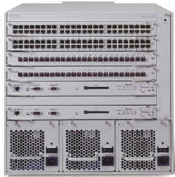
Configuracion Puerto Management Passport Serie 8600
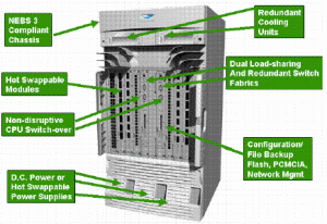
Existen 3 vias de asignacion de direcciones Ip en el Passport 8600 Series Switch:
1 Usando la IP address asignada a VLAN
2 Usando la IP address address asignada a el modulo CPU (8190SM, 8690SF, or 8691SF)
3 Usando el mgmt virtual IP address.
– Para asignar una IP address a unaVLAN, ejecutar lo siguiente desde CLI:
1 config vlan <vlan ID> ip create <ip address/subnet mask>
2 save config
– Para configurar una IP address a la CPU, ejecutar lo siguiente desde CLI:
1 config bootconfig net mgmt ip <ip address> <subnet mask> cpu-slot<value>
2 save bootconfig
– Para asignar una IP address a el puerto mgmt virtual, ejecutar desde CLI:
1 config sys set mgmt-virtual-ip < ip address > <subnetmask>
2 save config
Nota: La Gestion de la Direccion IP Virtual Funciona conjuntamente con las direcciones asignadas a una o a las dos CPU´S, solo se asigna una direccion Virtual y no una a cada CPU , no es posible cambiar esto, es una caracteristica que se implementa al activar las CPU´S en el Switch.
A partir de aquí ya podremos; copiar desde una sesion de TFTP o arrancar el Device manager de Nortel para configurar el Passport.
En caso de arrancar en Modo MONITOR tambien podremos configurar el puerto de management para utilizar el TFTP, si hiciera falta lo habilitariamos:
1 config bootconfig flags tftpd true
2 save bootconfig
3 reset
Los ficheros existentes en la flash, solo utilizaremos 4 de ellos:
Xxaxxxx.img : Que es una imagen de runtime , suele haber la cargada actualmente y la de 2ª carga
Xxbxxxx.img : Imagen del bootcode, esta es la usada por el boot monitor para trabajar, tambien suele
haber 2.
Boot.cfg : Archivo donde guarda el switch los paths de carga de imágenes, asi como la configuracion
mas basica como el puerto de mgmt. Si se elimina suele dar un mensaje de error de
carga y entrariamos en MONITOR para copiar uno correcto.
Config.cfg : Puede llamarse asi o de otra manera, es el archivo donde guarda la configuracion a nivel de
Vlan, politicas, snmp, etc… Suele cargarse desde Device Manager. Salvar ka runtime
config y la Bootconfig al salir, pinchando en el Chasis.
Generalidades
En los passport series 8600, para eliminar algun archivo de flash a de pcmcia utilizaremos el commando rm, una vez borrado no se recupera.
La Ip de management no puede ser de la misma red que la de la Vlan por defecto ( Vlan1)
Si queremos entrar en modo Boot Monitor al reiniciar el switch nos dejara 3 segundos para para el auto boot, presionar espaciador y entraremos.
Para configurar desde aquí el puerto de management haremos lo siguiente:
Monitor# net mgmt
Monitor/net/mgmt#ip xxxx.xxxx.xxxx.xxxx/xx
Monitor/net/mgmt#enable true
Con esto asignaremos una ip y habilitaremos el uso del puerto, Para conseguir funcionalidad directa con el portatil, necesitaremos un cable cruzado.
A partir del release 3.5.0 necesitaremos minimo de 128Mb de Ram , aconsejable un Ram Upgrade Kit de 256Mb.
La sintaxis de comando para copiar desde tftp seria el siguiente:
Copy /flash/p80a3500.img 192.0.0.75:p80a3500.img ó
Copy 192.0.0.75:config.cfg /flash/config.cfg
Si queremos hacer una copia de un archivo existente con diferente nombre usaremos lo siguiente:
Copy /flash/config.cfg /flash/config1.cfg
Posted in Hardware, Networking, Redes
Problemas Inicio en Windows XP / Vista / 7
Encontrarse con el error típico de inicio en Windows Xp NTLDR IS MISSING o FALTA BOOTMGR en Windows 7 es lo mas frecuente cuando se ha degradado el sistema de arranque del sistema operativo. Lo primero y será intentar si con un simple CHKDSK /P solucionamos el problema, para ello; arrancaremos con el CD del sistema operativo que tengamos instalado, es IMPORTANTE que respetemos la versión HOME o PROFESIONAL a la hora de arrancar desde CD, si no lo mas seguro es que tengamos problemas posteriores o incluso no reconozca la instalación de nuestro sistema operativo.
– Empecemos con Windows XP, ya sea Profesional o Home
1. Arrancamos de CD, asegurándonos que tenemos seleccionado el arranque en primer lugar del dispositivo CD/DVD en la BIOS de nuestra Placa Base.
Pulsaremos R para iniciar la consola de recuperacion y tener acceso a el comando CHKDSK.
Elegiremos la instalacion que queramos recuperar por defecto 1: C:Windows
Nos pedira Password de Administrador.
Una vez en el Prompt c: teclearemos CHKDSK /P e Intro
Una vez termine nos indicara si ha habido alguna incidencia, reiniciaremos y comprobaremos si arranca con normalidad, si es asi hemos terminado el proceso, si no, seguimos al sguiente paso.
2. Volvemos a ejecutar el punto 1. pero en vez de teclear chkdsk en la consola de recuperacion una vez arrancado desde CD/DVD vamos a ajecutar otros comandos de recuperacion diferentes.
C: fixmbr e Intro
C: fixboot e Intro
C: bootcfg /rebuild e intro
Con este metodo y si no hay ningun problema Hardware, como por ejemplo algun sector dañado en el Disco Duro, tendriamos que recuperar el inicio del sistema.
– Si Nuestro Sistema es WINDOWS 7 o WINDOWS VISTA
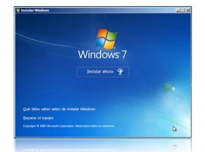
1. Introduciremos el DVD de Instalacion de Windows ,
2. Seleccionaremos el Idioma a utilizar.
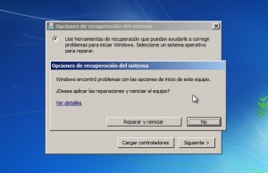
3. En la ventana inicial de Instalacion elegir REPARAR EL EQUIPO.
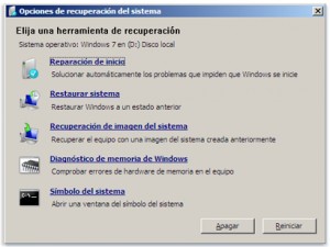
4. En el siguiente Menu, elegiremos la opcion de REPARACION DE INICIO.
5. Si ha encontrado algun problema nos dara la opcion de rapararlo, seleccionar REPARAR Y REINICIAR.
Si con este Procedimiento has podido soluccionar el Problema, ya hemos terminado , si no pasamos al paso siguiente.
6. Volvemos a repetir los pasos 1, 2, 3 y en el paso 4, elegimos SIMBOLO DE SISTEMA.
7. Nos aseguraremos de que la particion que tenemos en el disco esta activa
c: diskpart
c: DISKPART> list disk
c: DISKPART> select Disk 0
Listaremos las particiones que tenemos en el sistema, generalmente si hemos instalado con el DVD de instalacion de Windows 7 nos crea una particion de 100MB que es la de sistema, si hemos adquirido un Pc o Portatil con el sistema preinstalado puede variar.
c: DISKPART> list partition
c: DISKPART> select partition 0
c: DISKPART> active
c: DISKPART> exit
8. Una vez que tengamos claro que es la particion activa, restauramos desde consola el sistema de inicio.
c: bootrec /fixmbr
c: bootrec /fixboot
c: bootsect /nt60 c: /force
9. Reiniciaremos y comprobaremos que el arranque de nuestro sistema es normal.
Posted in Sistemas Operativos, Software
Errores Impresoras TektroniX
7,005.47
The drum Maintenance home sensor actuated, but not at the expected time
Run diagnostics to verify clutch and sensor operation. Also verify that the drum
maintenance shaft is properly assembled.
2,000
System fault I/O Board.
2,001.40
The engine cannot detect the presence of the right I/O board.
2,002.40
The engine cannot detect the presence of the left I/O Board.
2,002.40
Engine firmware was unable to initialize.
2,003.62
The engine firmware was unable to start the service diagnostics task.
4,001.40
Failure reading print head NVRAM data.
4,002.41
Print head NVRAM data was all 0s.
4,003.42
Print head NVRAM was all 1s.
4,004.43
Print head NVRAM checksum failure. The data within the print head has
been corrupted.
4,006.67
This indicates that an undefined message was found by the processor.
4,013.43
The print head is unable to move on its tilt axis, because it is colliding with
something. (head restraint pin,cap,poorly installed ink loader,screwdriver.)
4,014.44
Calibration failure.
4,015.45
The engine spent over 20 minutes in the print head adjust state. Remove the
adjustment tools and cycle power.
4,016.46
The print head format number is not understood by this version of engine
firmware. Verify the correct print head is installed. Replace the print head.
4,017.47
Ambient temperature has fallen to less than 10 degrees. Something may be
wrong with the print head.
4,018.48
The print head temperature dropped below the head-clean-threshold’ Check
the heater.
4,019.40
Calibration failure Replace the print head.
4,020.41
Declared when the printer is booted and the head/cap contact flag is set in
NVRAM.
4,021.42
Declared when the printer is booted and the drum is dirty.
4,023.66
Dangerous process motor motion detected.
4,029.63
Head calibrate task spawn failed. This may be due to a low memory
condition.
4,032.66
Undefined result in pc_ process_result().
4,035.60
Bad status message in pc_ process_status().
4,040.65
Re-entrant call to halt detected I/O right has been known to cause this fault
code.
4,046.62
Dangerous process motor detected.
4,051.67
Bad command result during Drum warm-up processing of a postscript
command message in pc _process_message().
4,059.66
Bad command result during Big Drop Flush Processing.
4,064.62
Bogus thermal state. Corrupt NVRAM device.
4,128.63
Bad command result waiting for fault to clear processing of a postscript
command
4,243.61
Some Phaser 850 printers were built with print heads that had different set
points for different print modes Replace the print head.
5,001.41
Drum-home sensor failure.
5,002.42
Y-axis position failure.
5,005.67
Bad ITC command in home state.
5,026.61
Missed ITC message during rendezvous.
6,000.41
Indication that motor coil is open or shorted.
7,001.43
There is a problem with the lower tray assembly or its installation.
7,001.65
Replace I/O board right.
7,004.46
The drum maintenance home sensor did not actuate or change state as
expected.
7,005.47
Drum maintenance home sensor actuated, but not at the expected time.
7,006.48
Drum maintenance home sensor actuated when no motion should have
occurred.
15,004.45
Most likely cause is a failed drum heater.
Posted in Hardware, Impresoras
Errores Impresoras LexmarK
Error 20
Input Paper Sensor was not triggered. Paper may be jammed at the
sensor. Remove toner cartridge for better access to jammed paper Replace pick
up rollers
Error 21
The exit sensor was not tripped in time Check for paper jam
Error 22
The exit sensor was not tripped in time. Check for paper jam
Error 23
Jam at the duplex unit. Remove paper from duplexer
Error 24
The defined paper size is too short to print data as formatted. Change
to correct paper size
Error 25
Input sensor tripped at wrong time.
Error 26
Duplex unit is installed but paper tray is not sensed.
Error 27
Envelopes/paper loaded are wrong size.
Error 28
Input sensor not made after pick attempt. Tray is empty or not
installed, paper jam in entry throat, or printer is requesting a manual feed.
Error 29
The output bin sensor has not been tripped
Error 30
Top Cover Open or Print Cartridge Missing Make sure the springmounted
pin on the print head shroud is installed properly and that it is detected
by the ramp on the print cartridge as the cover closes. The pin should enter the
tower on the HVPS and depress the cover switch.
Error 32
Wrong Print Cartridge installed . The installed print cartridge is not
supported by the Optra printer
Error 37
Insufficient Collation Memory Memory is too full to collate the print
job.
Error 38
38 Memory Full Memory used to store pages is full. To verify that the
printer recognizes all the installed memory, go to the user menus and print the
“Print Menus” test page. Make sure the memory shown on the printout matches
the installed memory.
Error 39
Page too complex to print. To verify that the printer recognizes all the
installed memory, go to the user menus and print the “Print Menus” test page.
Make sure the memory shown on the printout matches the installed memory.
Error 43
Font card format not supported by printer
Error 44
Defective font card installed in font slot.
Error 47
Font Card Removed While Printing Printer needs data on removed
card.
Error 52
Flash Full Not enough flash memory for data requested to be stored.
Error 53
Unformatted or Defective Flash Flash problem at POR or while
Error 54
Serial Error – Framing or parity error on serial.
Error 58
Duplex Not Attached Duplex is electrically connected but no longer
mechanically attached, and printer top cover is closed.
Error 59
Duplex Cover Open Top cover of duplex unit is sensed open.
Error 62
Disk Full Not enough disk space for data that has been requested to be
written to disk.
Error 63
Unformatted or Defective Disk The printer will ignore a disk it senses
as defective. Run the Quick Disk Test. If the test fails, the disk is defective or the
data on track1 is bad. If the Quick Disk Test passes but the disk does not work,
run the Disk Test/Clean (2 hr. test). Replace the disk if instructed by the operator
panel.
Error 7X
Network Card Codes These user codes are documented in various
network card user manuals
Error 80
Network Card Codes These user codes are documented in various
network card user manuals.
Error 80
Printer has reached 200,000 prints without maintenance count reset.
Install maintenance kit and reset maintenance message
Error 88
Toner Low Toner sensor detects low toner. Replace toner cartridge
Error 90X
Software Error Unrecoverable software error. If one of these errors
appeared during POST, or while the printer was idle (not printing or receiving
data), or while trying to print one of the internal test pages, replace the system
board. If the error appeared while sending a job from the host to the printer, turn
the printer off, then turn it on and try again.
Error 917
Transfer Roll Error Cannot start servo operation. Verify correct cable
connections from the Engine board to the HVPS. Make sure there is continuity
between the transfer roller and its contact on the HVPS; replace the transfer roll
if the continuity is correct. If there is no continuity, make sure the HVPS goes
back when depressed, and make sure the left bearing of the transfer roll is
making proper contact.
Error 920
Fuser Error Fuser is below temperature while printing. Replace fuser
Error 921
Fuser is below standby temperature when idle. Replace fuser
Error 922
Fuser failed to reach standby temperature. Replace fuser
Error 923
Fuser is too hot while printing or when idle. Replace fuser
Error 924
924 Fuser Error – Open circuit detected in thermostat circuit. Replace
fuser
Error 927
Fan Stalled Check fan for binding or defective bearing – Replace Fan
Error 928
Erase lamp assembly missing or disconnected
Error 931
Print head error – No first sync Replace printhead
Error 932
Lost hsync
Error 934
Print head Error – Lost Lock condition
Error 935
Print head Error – Mirror motor unable to reach operation speed
Posted in Hardware, Impresoras
Errores Impresoras OKI
1 Machine Check Exception
A problem has been detected in the printer hardware
2 DSI Exception
The printers main logic has attempted to look up an invalid address.
3 ISI Exception
The printers main logic has attempted to read the next instruction,
which has failed to execute for some reason.
4 Alignment Exception
The printers main logic cannot access the memory for some
reason.
5 Program Exception
The printers main logic has issued an exception code.
6 Floating-point Unavailable Exception
A floating-point instruction is executed
when the MSR floating point enable bit is set to Disable.
7 Instruction Address Breakpoint Exception
The printers main logic has attempted
to look up an invalid address.
20 CU ROM Hash Check Error 1
CU ROM hash check error has been found. Check
reproducibility if possible.
21 CU ROM Hash Check Error 2
The printers CPU has a checksum error in it’s
memory.
23 CU ROM Hash Check Error (resident)
Seek service if restarting the printer does
not correct the problem.
25 CU ROM Hash Check Error (DIMM2)
Seek service if restarting the printer does
not correct the problem.
30 CU Slot1 DIMM RAM
Check Error An error has been detected in operation
checks on the RAM in slot 1
31 CU Slot2 DIMM RAM
Check Error An error has been detected in operation
checks on the RAM in slot 2
35 Slot1 RAM Spec Error
Check the specification and install in slot 1 RAMs
supported by the product
40 CU EEPROM Error
The EEPROM mounted on the CU board needs to be
replaced
41 CU Flash Error
The CU Flash needs to be replaced
43 Flash File System
Version Mismatch Seek Service if restarting the printer and
initialising the flash memory does not correct the problem
42 Flash File System Error
Seek Service if restarting the printer and initialising the
flash memory does not correct the problem
43 PS Flash File System Error
An Flash Memory error has occured and the printer
needs to be serviced if restarting the printer does not correct the problem
51 CU Fan Error
The CU cooling fan needs to be replaced if restarting the printer
does not correct the problem
70 Postscript Failure
An error has been detected in your printer’s Postscript Core.
72 Engine Communication Error
A communications error has occurred between CU
and PU boards.
73 H/W Overrun Detect
An error has been detected in your printer’s hardware input
area.
74 F/W Overrun Detect
Occurs when the firmware is unable to set video data in
response to video DMA’s data request.
75 VIC Limiter
An error has been detected in your printer’s
80 Parameter I/O Error
An error has been detected in your printer’s Input/Output
area.
81 Parameter Consistency
Check Error The EEPROM and flash memory
reformatted and initialized.
102 Engine RAM Error
An error has been detected in your printer’s engine RAM.
103 Engine SRAM Error
An error has been detected in your printer’s engine SRAM.
104 Engine EEPROM Error
An error has been detected in your printer’s engine
reading/writing the EEPROM at power-up.
105 Engine EEPROM
Missing Error An error has been detected in your printer’s
Engine
106 Engine Control Error
An error has been detected in your printer’s Engine
Controller.
122 Power Supply Fan Motor
Error An error has been detected in your printer’s
Power Supply Fan Motor.
123 Humidity Sensor
An error. has been detected in your printer’s Humidity Sensor
124 Temperature Sensor
An error has been detected in your printer’s Temperature
Sensor.
127 Fuser Unit Fan Error
An error has been detected in your printer’s Fuser Unit
Fan Error.
131 LED Head Missing, Color: Yellow
When yellow LED head connection cannot
be detected
132 LED Head Missing, Color: Magenta
When magenta LED head connection
cannot be detected
133 LED Head Missing, Color: Cyan
When cyan LED head connection cannot be
detected.
134 LED Head Missing, Color: Black
When black LED head connection cannot be
detected.
140 Drum Up/Down, Color: Yellow
An error has been detected in your printer’s
Yellow Drum
141 Drum Up/Down, Color: Magenta
An error has been detected in your printer’s
Magenta Drum.
142 Drum Up/Down, Color: Cyan
An error has been detected in your printer’s Cyan
Drum.
150 Drum Fuse cut NG, Color: Yellow
An error has been detected in your printer’s
Drum Fuse.
152 Drum Fuse cut NG, Color: Cyan
An error has been detected in your printer’s
Drum Fuse.
153 Drum Fuse cut NG, Color: Black
An error has been detected in your printer’s
Drum Fuse.
155 Fuser Unit Fuse cut NG
An error has been detected in your printer’s Fuser Unit.
154 Belt Unit Fuse cut NG
An error has been detected in your printer’s Belt Unit.
160 Toner Sensor Error, Color: Yellow
An error has been detected in your printer’s
Toner Sensor.
161 Toner Sensor Error, Color: Magenta
An error has been detected in your
printer’s Toner Sensor.
162 Toner Sensor Error, Color: Cyan
An error has been detected in your printer’s
Toner Sensor.
163 Toner Sensor Error, Color: Black
An error has been detected in your printer’s
Toner Sensor.
170 Upper Thermistor,
State: Short An error has been detected in your printer’s
Upper Thermistor.
171 Upper Thermistor
, State: Open Restart the printer. If the problem continues the
printer will need to be serviced
172 Upper Heat Temp
, State: High An error has been detected in your printer’s
Upper Heat Temp.
173 Upper Heat Temp, State:
Low Turn the printer off to let it cool down, then
restart the printer.
181 I/F Error, Loc. Duplex
An error has been detected in your printer’s Duplexer.
182 I/F Error, Loc. Tray2
An error has been detected in your printer’s Tray2.
187 I/F Error, Loc. Control Pnale
An error has been detected in your printer’s
Control Panel.
190 System Memory Overflow
An error has been detected in your printer’s System
Memory Overflow.
191 Page Memory Overflow
An error has been detected in your printer’s Page
Memory Overflow.
200 PU F/W download Check Sum Error
Error during PU flash download
201 PU F/W Flash Write Error
An error has been detected in your printer’s PU F/W
Flash Write Error.
202 PU F/W Flash Data Missing
An error has been detected in your printer’s PU
F/W download Check Sum Error.
203 Engine Page Sequences IMAGACK Error
An error has been detected in your
printer’s Engine Page Sequences IMAGACK Error.
204 EnginePageSequences IMGSET
Error An error has been detected in your
printer’s Engine Page Sequences IMGSET Error.
Posted in Hardware, Impresoras
Errores Impresoras Konica Minolta
Temperature Control Error
1.
Repower the printer. If problem is not resolved go to step 2.
2.
Improve the connection between the fusing unit and its connectors. Remove the
fusing unit and reset.
3.
Does heat lamp (H1) come on when the power supply is turned on?
NO, Replace the fusing unit.
4.
Does heater lamp (H2) come on when the power supply is turned on?
NO, Replace the fusing unit Replace power supply circuit board.
5
. Replace PWB-A.
OC Pwr Supply Fan
Does the power supply fan motor (M8) operate during power up?
NO, Ensure the connection of the connector (PJ16A) is secure.
1
. Replace fan motor.
2.
Replace PWB-A.
0D Engine Fan
1.
Does the ozone fan motor (M9) operate during power up?
NO, Ensure the connection of the connector (PJ28A) is secure.
2.
Replace the fan motor.
3.
Replace PWB-A.
0E Suction Fan
1
. Does the suction fan motor (M7) operate during power up?
NO, Ensure the connection of the connectors (PJ3A) is secure.
2.
Replace fan motor.
3.
Replace PWB-A.
0B Xfer Fan Belt
1.
Does the toner suction fan motor (M11) operate during power up?
NO, Ensure the connection of the connectors (PJ30A) is secure.
2
. Replace fan motor.
3.
Replace PWB-A.
0F Fusing Unit Fan
1.
Does the fusing fan motor (M10) operate during power up?
NO, Ensure the connection of the connector (PJ29A) is secure.
2.
Replace the fan motor.
3
. Replace PWB-A.
08 Main Motor
1.
Does the transport motor (M1) operate during power up?
NO, Ensure the connection of the connector (PJ21A) is secure.
2.
Replace the transport motor.
YES, Check if there is excessive load on any of the rollers,gears,etc.
3
. Replace PWB-A.
09 Fusing Motor
1.
Does the fusing motor (M4) operate during printing?
NO, Ensure the connection of the connector (PJ22A) is secure.
YES, Check if there is excessive load on any of the rollers, gears, etc.
2
. Replace PWB-A.
20 Fus Retract
1.
Is the fusing unit floating?
YES, Mount the fusing unit properly.
2
. Does the fusing pressure motor (M5) operate during printing?
NO, Ensure the connection of the connectors (PJ25A) is secure.
3.
Replace the fusing unit.
YES, Check if there is excessive load on any of the rollers, gears, etc.
4.
Replace the fusing pressure position sensor.
5
. Replace the pressure roller release sensor.
6
. Replace PWB-A.
Laser Unit Error
1.
Check that the connections between the connectors for the laser unit control section
and polygon motor are correct.
2
. Ensure the connection of the connector (PJ27A) is secure.
3
. Ensure the connection of the connector (PJ12A) is secure.
YES, Replace laser unit.
4
. Replace laser safety switch.
5
. Replace PWB-A.
16 Xfer Belt Rot
1
. Does the image transfer belt rotate during printing?
NO, Check if the image transfer belt unit is properly positioned and repair it.
YES, Replace the image transfer belt unit.
2
. Replace PWB-A.
15 Xfer Belt Cln
1.
Does the belt cleaner motor rotate during printing?
NO, Ensure the connection of the connectors (PJ32A and PJ33A) are secure.
2
. Ensure the connection of the connectors (PJ51and PJ61) are secure.
3
. Turn the cam gear by hand and check if the sensor light breaker breaks the light.
YES, Replace the belt cleaner release sensor.
4
. Replace PWB-A.
AIDC Error
1
. Is the AIDC sensor dirty?
YES, Operate unit release lever A clean the AIDC sensor.
2
. Does the transfer belt rotate during printing?
YES, Replace the image transfer belt unit.
3
. Replace OPC drum.
4
. Replace high voltage circuit board.
5
. Replace PWB-A.
14 Xfer Roller
1
. Does the image transfer roller pressure solenoid one-way clutch have a hook?
NO, Replace the one-way clutch.
2
. Remove the multipurpose tray cover and check if the image transfer roller pressure
sensor light breakeer plate rotates.
NO, Replace the image transfer roller pressure solenoid.
YES, Replace the image transfer roller pressure sensor.
3.
Replace PWB-A.
17 Toner Rack
1.
Does the rack motor (M3) operate during printing?
NO, Remove and reconnect connectors PJ32A and PJ33A.
2.
Turn the power off, push the rack release button and turn the rack by hand.
YES, Replace the black cartridge home position sensor. (PC60)
NO, Examine assembly, toner cartridges, or other components associated with the
rack for binding of the rack rotational movement.
3.
Replace PWB_A.
22 Man Tray Lift
1
. Does the paper in the multipurpose tray press against the paper take-up roller?
NO, Check media in multipurpose tray to ensure it is not overloaded.
2
. Use paper that meets printer specification
3.
Is there a tab on the one-way clutch for the multipurpose tray take up roller?
NO, Replace the gears for the one-way clutch.
YES, Replace the paper take-up solenoid for the multipurpose tray.
4
. Replace PWB-A.
21 Trans Det Sensor
1.
Are the light emitting and receiving ports for the OHP sensor dirty?
YES, Clean the OHP sensor port.
2
. Does the prism for the OHP sensor have paper dust or particles on it?
YES, Clean the reflector plate for the OHP Replace PWB-A.
29 Mem Malf Counter
1.
Cycle power switch on and off. Does the error reoccur?
YES, Replace the PWB-A.
2A Mem Malf Data
1
. Cycle power switch on and off. Does the error reoccur?
YES, Replace the PWB-A.
2B Mem Malf Access
1.
Cycle power switch on and off. Does the error reoccur?
YES, Replace PWB-A.
2C Mem Malf Install
1.
Cycle power switch on and off. Does the error reoccur?
YES, Inspect associated wiring between the memory board and the PWB-A.
2.
Any discrepancies found with the wiring YES Repair as needed.
NO, Replace PWB-A.
04 Main Unit
1.
Cycle power switch on and off.
2
. Does the error reoccur?
YES, Replace the PWB-A.
05 Flash Rom
1
. Cycle power switch on and off.
2
. Does the error reoccur?
YES, Replace the PWB-A.
Posted in Hardware, Impresoras
Errores Genericos Impresoras HP ( II Parte )
Access Denied Menus Locked
The control panel function you are trying to use has been locked by the network
administrator to prevent unauthorized access. Ask the network administrator to unlock
the function.
Bad Duplexer Connection
The duplexer is not correctly installed.
1
. Ensure that the right-angle power cord that shipped with the printer is being used.
2
. Turn the printer off.
3
. Remove and reinstall the duplexer.
4
. Turn the printer off and back on.
5
. If the message persists, make sure the duplexer is connected and the connector is
not damaged.
6
. Replace the duplexer.
Check Input Device alternates with Paper Path Open Please Close
It The optional input tray cannot feed print media to the printer because a door or
paper guide is open.
1
. Check the doors and paper guides and close any that are open.
2
. If doors and trays are closed, check tabs and sensor levers in the tray for proper
operation. Replace any defective tabs or sensors.
3
. Replace the PCA controller in the feeder.
Check Output Device alternates with Close Output Delivery Path
The optional output device is not properly connected to the printer.
1.
Ensure the optional output device is fully seated and properly installed.
2
. Check any doors on the output device and verify they are closed.
Disk Device Failure
The EIO disk had a critical failure or fatal error.
1
. Reseat the EIO disk.
2.
Remove the EIO disk and replace it with a new one.
Disk File Operation Failed
Requested operation could not be performed (for example, attempting to download a
file to a nonexistent directory).
1.
Check the file name and the directory name.
2
. Reseat the EIO disk.
3
. Retry the operation.
Disk is Write Protected
The EIO disk is protected, and no new files can be written to it. Disable the write
protection through HP Resource Manager.
EIO Disk [x] Not Functional
EIO disk is not working correctly.
1
. Reseat the EIO disk in slot [X].
2.
Remove and replace the EIO disk in slot [X].
Env Feeder Load [Type] [Size]
A job has been sent to the envelope feeder and the feeder is empty, the wrong size is
loaded in the feeder, or the type and size are set incorrectly on the control panel.
1
. Load the requested envelope type and size into the envelope feeder.
2
. Make sure the envelope size and type are set correctly from the paper-handling
menu in the printer control panel.
3
. Press GO if the desired envelope is already loaded in the feeder.
4
. Press -VALUE+ to scroll through other available types and sizes.
5
. Press SELECT to accept the alternate type or size.
Envelope Feeder Size = [xxxxx]
The printer is asking what size envelopes have been loaded in the envelope feeder. In
response, you can take either of the following actions:
1
. Press SELECT to accept the current envelope size.
2
. Press -VALUE+ to change the size and then press SELECT to accept the new size.
If you do not press any buttons, the message disappears in about one minute.
Note:
Changing the size here changes the default for the envelopefeeder size in the
paper-handling menu.
Envelope Feeder Type = [xxxxx]
The printer has received a job under the following conditions: The envelope type the
job requested is not available in the printer. Envelopes have been placed in the
envelope feeder (thus triggering the paper sensor). You can take either of the
following actions:
1.
Press SELECT to accept the paper type and then press GO.
2
. Press +VALUE- to change the type, press SELECT to accept the new type, and
then press GO to continue.
File System is Full
The disk file system is full.
1
. Delete all unnecessary files from the EIO disk and then try again.Use HP Resource
Manager to download or delete files and fonts. (See the software help for more
information.)
2
. Advise the customer to increase the permanent storage (use a larger EIO disk or add
a RAM DIMM).
Flash Device Failure
The flash DIMM had a critical or fatal failure.
1
. Reseat the flash DIMM and ensure it is locked into place.
2
. Remove the flash DIMM and replace it with a new one.
Flash File Operation Failed
The requested operation could not be performed (for example, attempting to download
a file to a nonexistent directory).
1.
Check the file name and the directory name.
2
. Reseat the flash DIMM. 3. Retry the operation.
Flash File System is Full
The flash file system is full. Delete unnecessary files from the flash DIMM and try
again. Use HP Resource Manager to download or delete files and fonts. (See the
software help for more information.)
Flash is Write Protected
The flash DIMM is protected and no new files can be written to it. Disable the write
protection through HP Resource Manager.
HP Toner Detected alternates with Press Go To Continue
The printer has detected that the toner cartridge is not a genuine HP toner cartridge
because it does not see or recognize the toner cartridges identification (model,
manufacturing date, and serial number).
1
. Make sure the toner cartridge is a genuine HP toner cartridge. A non-HP toner
cartridge will produce this error.
2
. If the HP toner cartridge is new, the Elabel (cartridge memory) is missing or has
been tampered with. Replace the toner cartridge.
Input Device Condition [XX.YY]
An input paper-handling device has a condition that needs attention before printing
can resume. 1st X = Device number in chain 2nd X= Device type (three types):
1
= Input 2 = Output 3 = Stapler/stacker unit YY = Device specific error 1. Turn the
printer off.
2
. Disconnect the cable to the input paper handling devices and then reconnect it.
3
. Ensure the device is properly connected and any doors or paper guides are properly
closed.
4
. Turn the printer on.
5
. See the documentation that came with the paper-handling device for assistance.
Install Duplexer
The printer is unable to print the current job because the duplexer is not installed or
not inserted correctly.
1
. Turn the printer power off. Install or reinsert the duplexer and ensure it is fully
seated.
2.
Ensure the right-angle power cord is used for the printer.
Install Toner Cartridge
The toner cartridge has been removed and must be reinstalled for printing to continue.
Reinstall the toner cartridge and ensure it is fully seated.
Install Tray [X]
The printer is unable to print the current job because the specified tray [X] is open or
not inserted correctly
1
. Reinsert the specified tray.
2
. Check for damaged tabs on the right side of the tray.
3
. Check for damaged tray sensor switches in the printer.
4
. Replace the PCA controller in the feeder
Loading Program [Number] alternates with DO NOT POWER OFF
Programs and fonts can be stored on the printers file system. At startup time, these
entities are loaded into RAM. (These entities can take a long time to load into RAM
depending on the size and number of entities being loaded.) The specifies a sequence
number indicating the current program being loaded. Wait for the program to load.
Manually Feed [Type] [Size]
One of the following occurred: – A manual feed was requested.-There is no media in
tray 1.- The wrong size of media is loaded. – The control panel is not set for the size
and type of media loaded.
1.
Load the requested paper into tray 1.
2
. Press GO (or READY on older printers) if the desired paper is already loaded in
tray 1.
3
. Press -VALUE+ to scroll through other available types and sizes.
4
. Press SELECT to accept the alternate type or size.
Memory Full Stored Data Lost
There is no available memory in the printer. The current job might not print correctly
and some resources (such as downloaded fonts or macros) might have been deleted.
Press GO to continue. Add more memory to the printer or to simplify the print job.
Memory Settings Changed
The printer changed its memory settings because it did not have enough memory to
use the previous settings for I/O buffering and resource saving. This usually occurs
after removing memory from the printer, adding a duplexer, or adding a printer
language. Press GO to continue. Add more memory to the printer or to simplify the
print job
Memory Shortage Job Cleared
The printer did not have enough free memory to print the entire job. The remainder of
the job will not print and will be cleared from memory. Press GO to continue. Add
more memory to the printer or to simplify the print job.
Offline
The printer is offline Press GO or READY or ONLINE to place the printer online.
Output Bin Full alternates with Clear Paper From [Binname]
The output bin is full and needs to be emptied. Remove the sheets from the output bin.
Paper Wrapped Around Fuser
Print media is wrapped around the fuser.
1.
Turn the printer off to keep the media from wrapping more firmly around the fuser.
2
. Open the top cover and remove the toner cartridge.
3
. Remove all the visible media.
4
. Leave the printer turned off and remove the fuser to remove any remaining print.
Perform Printer Maintenance
To ensure optimum print quality, the printer prompts the customer to have routine
maintenance installed. Install the printer maintenance kit. You must reset the
maintenance page count after performing printer maintenance.
Note:
The printer maintenance kit is a consumable item and is not covered under
warranty.
Processing Cleaning Page
The printer is conducting the manual cleaning-page process. Wait for the job to finish.
This can take up to 2.5 minutes.
Processing Job
The printer is processing a job. Wait for the job to finish. This can take several
minutes for a complex print job.
RAM Disk Device Failure
The RAM disk had a critical or fatal failure.
1
. Reseat the RAM disk.
2
. Replace the RAM disk.
RAM Disk File Operation Failed
The requested operation could not be performed (for example, attempting to download
a file to a nonexistent directory).
1
. Check the filename and directory name.
2
. Reseat the RAM disk.
3
. Retry the operation.
Posted in Hardware, Impresoras
Errores Genericos Impresoras HP (I Parte )
10.00.00 Supplies Memory Error alternates with 10.10.00
The printer is unable to read the electronic info on the print cartridge Replace print
cartridge 13.XX Paper Jam [Location]
Media is jammed at the specified location (and possibly at other locations). If the
message persists after all jams have been cleared, a sensor or sensor lever might be
stuck or broken. For all jam messages, do the following:
1.
Remove jammed print media from the specified location. Check the entire paper
path for other pieces of media in the path.
2.
Open and close the top cover to clear the message.
3.
Check sensors and flags in the paper path for proper operation.
3.0 Paper Jam [Location]
A non-specific paper jam occurred.
1.
Remove jammed media from the specified location.
2.
Verify the paper tray is fully closed.
3.
Inspect and/or replace the feed and separation rollers.
4.
Ensure there is no obstruction in the path, such as a torn piece of paper.
5.
Open and close the top cover to clear the message.
6.
Check sensors and flags for proper operation.
13.1 Paper Jam Open Input Trays
Paper-delay jam at paperfeed area.
1.
Ensure that paper trays are loaded and adjusted properly so media can feed from the
tray. It might be necessary to reduce the stack height of media in the tray.
2.
Check the input area for obstructions such as media in the path. Also check to see if
the registration assembly damaged or unseated.
3.
Replace any defective sensors or flags.
4.
Verify the media meets the specifications.
5.
Check the pickup feed and separation rollers for unusual wear. Replace as needed.
6.
Rotate the media in the input tray by 180 and/or turn it over.
13.2 Paper Jam Open Input Trays
Paper-stopped jam at paper-feed area.
1.
Check the input area for obstructions such as paper in the path. Also check to see if
the registration assembly is damaged or if the transfer roller is out of place.
2.
Replace any defective sensors or flags.
3.
Ensure the media does not exceed the maximum length.
4.
If multiple sheets are feeding, it might be necessary to fan the media and reduce the
stack height. Also, replace separation pad.
5.
Verify that the fuser is properly installed.
13.10 Paper Jam Check Duplexer Jam at duplexer.
1.
Check the duplexer and the rear area of the printer for obstructions or damage.
2.
Check the duplexer for proper operation. Replace the duplexer if a sensor is
defective.
13.14
For Laserjet 5si. This error is caused by a defective paper control PCA Replace paper
control PCA.
13.20 Paper Jam Check Rear Door
Media stopped in the paper path during power on or when the top door was closed.
1.
Remove all media in the paper path, and then open and close the top cover.
2.
If the message persists after all media is removed: Check if media is jammed in the
prefeed area. Replace any defective sensors or flags
13.21 Door Open Jam
The top cover was open while printing.
1.
Clear the jam and close the top door.
2.
If the message persists, check the top door switch for proper operation.
13.5 Paper Jam Check Rear Door
Paper-delay jam at fuser.
1.
Check the transfer roller and small media belt to ensure they are operating and can
feed print media.
2.
Check the paper path for obstructions at the transfer roller, toner cartridge, paper
feed assembly, and fuser.
3.
Replace any defective sensors or flags.
4.
Turn the media stack over and/ or rotate it by 180 in the input tray.
13.6 Paper Jam Check Rear Door
Paper-stopped jam at fuser.
1.
Check the paper path for obstructions at the fuser and output/delivery area.
2.
Replace any defective sensors or flags.
13.99 Paper Jam [Location]
A non-specific paper jam occurred.
1.
Remove jammed media from the specified location.
2.
Verify the paper tray is fully closed.
3.
Inspect and/or replace the feed and separation rollers.
4.
Ensure there is no obstruction in the path, such as a torn piece of paper.
5.
Open and close the top cover to clear the message.
6.
Check sensors and flags for proper operation.
20 Insufficient Memory
The printer received more data than can fit in available memory. You might have tried
to transfer too many macros, soft fonts, or complex graphics. Press GO to print the
transferred data (some data might be lost). Advise the customer to simplify the print
job or install additional memory
21 Page too Complex
The data (dense text, rules, raster or vector graphics) sent to the printer is too complex
Press GO to print the transferred data. (Some data might be lost.) Advise the customer
to simplify the print job.
40 EIO x Bad Transmission
The connection has been broken between the printer and the EIO card in the specified
slot. (Data loss might occur in this situation.)
1.
Press GO to clear the error message and continue printing.
2.
Reseat the EIO card in slot [X].
41.3 Unexpected Paper Size
The printer detected a media size different from what it was expecting. This is
typically caused if two or more sheets stick together in the printer or if the tray is not
properly adjusted.
1.
Reload the tray with the correct print media size.
2.
Ensure that media in the tray is loaded under the front and back tabs.
3.
If you are printing from tray 1, verify that the correct paper size is selected in the
control panel.
4.
If you are printing from tray 2, 3, or 4, verify that the three paper-size adjustments
(length guide, width guide, size-selector switch) on the paper tray have been made
correctly. Make sure the media is under the corner tabs.
5.
After performing the actions above, press GO. The page containing the error will
automatically be reprinted if jam recovery is enabled. (Or, you might want to press
CANCEL JOB to clear the job from the printers memory.)
41.5 Printer Error
The media reached the PS102 or PS103 sensor too early.
1.
This error usually occurs with smooth media, such as transparencies or labels. If the
problem persists when using tray 1, load media one sheet at a time. If the problem
persists when using trays 3 and 4, replace the feed and separation rollers.
2.
Check sensors PS102 and PS103 for proper operation.
41.X Printer Error
A temporary printing error has occurred. The page containing the error will
automatically be reprinted. If the error persists:
1.
Reseat the connections to the laser scanner and then to the engine controller board.
2.
Replace the laser scanner.
3.
Replace the engine controller board.
49.XX Printer Error
A firmware error occurred
1.
Press CANCEL JOB to clear the print job from the printer memory.
2.
Turn the printer off, and then turn the printer on. Try printing a job from a different
software application. If the job prints, go back to the first application and try printing a
different file. (If the message only appears with a certain software application or print
job, contact the software vendor for assistance.)
3.
If the message persists with different software applications and print jobs,
disconnect all cables to the printer that connect it to the network or printer.
4.
Turn the printer off.
5.
Remove all memory DIMMs or third-party DIMMs from the printer. (Do not
remove the firmware DIMM in the lowest DIMM slot.)
6.
Remove all EIO devices from the printer.
7.
Turn the printer on.
8.
If the error no longer exists, install each DIMM and EIO device one at a time,
making sure to turn the printer off and back on as you install each device.
9.
Replace a DIMM or EIO device if you determine that it causes the error.
10.
Remember to reconnect all cables that connect the printer to the network or
computer.
11.
If the error persists, replace the firmware DIMM.
12.
Replace the formatter.
50.4 Printer Error
A problem exists with the customers line voltage.
1.
Remove the printer from any UPS supplies, additional power supplies, or power
strips.
2.
Plug the printer into a wall outlet and see if this resolves the problem.
3.
If the printer is already plugged into a wall outlet, try another power source in the
building that is independent of the one currently being used.
4.
The line voltage and current source at the printer location might need to be
inspected to ensure that it meets the printer’s electrical specifications.
50.X Printer Error
A fuser error has occurred.
1.
Turn the printer off, wait 10 minutes, and then turn the printer on.
2.
If the message persists, reseat the fuser. If that does not work, replace the fuser. To
check the fuser, turn the printer off and remove the fuser. Measure the resistance
between the fuser connectors. If it is not within the proper range, replace the fuser. If
there is not continuity between the fuser connectors neutral and hot with the fuser
removed, replace the fuser. If the problem is not related to the fuser, replace the
engine controller board.
51.X Printer Error
A loss of beam-detect occurred. X description: 1 = Beam-detect error 2 = Laser error
1.
Press GO. The page containing the error will automatically be reprinted.
2.
Turn the printer off and then on.
3.
Reseat cables to the laser/ scanner and engine controller.
4.
Replace the laser/scanner.
5.
Replace the DC controller.
52.X Printer Error
The laser scanner speed is incorrect. X description: 1 = Scanner startup error 2 =
Scanner rotation error
1.
Press GO. The page containing the error will automatically be reprinted.
2.
Turn the printer off and then on.
3.
Reseat cables to the laser/ scanner and engine controller.
4.
Replace the laser/scanner.
53.XY.ZZ Printer Error
There is a memory error with an accessory. The DIMM that caused the error will not
be used. Values of X, Y, and ZZ are as follows:
X = DIMM type 0 = ROM 1 = RAM
Y = Device location 0 = internal memory (ROM or RAM) 1 to 4 = DIMM slots 1, 2,
3, or 4
ZZ = Error number0, 1, 2 = Unsupported o unrecognized memory 3 = Failed RAM
test 4, 5 = Exceeded maximum RAM or ROM size 6 = Invalid DIMM speed 7 =
DIMM reporting information incorrectly 8 = DIMM RAM parity error 9 = ROM
needs to be mapped to an unsupported address 10 = DIMM address conflict 11 = PDC
XROM out of bounds 12 = Unable to make a temporary mapping
1.
Turn the printer off, and reseat or replace the specified DIMM.
2.
Try the DIMM in another slot. (The firmware DIMM must remain in slot #4-the
lowest DIMM slot.)
3.
Replace the DIMM that caused the error.
54.1 Remove Sealing Tape
The toner cartridge has been installed without removing the sealing tape.
1.
Open the top cover and remove the toner cartridge.
2.
Pull the sealing tape tab to remove the strip.
3.
Reinstall the toner cartridge and close the top cover.
54.2 Printer Error
Indicates a problem exists with the carousel assembly. Either the carousel is not
rotating or the sensor has failed.
1.
Turn printer off then on to reset printer.
2.
Open the color toner door and look for an obstruction. If necessary, remove the
toner cartridges individually by manually releasing the carousel brake and rotating the
carousel around to each cartridge
54.4 Printer Error alternates with Cycle Power to Continue
A problem exists with the customers line voltage.
1.
Remove the printer from any UPS supplies, additional power supplies, or power
strips.
2.
Plug the printer into a wall outlet and see if this resolves the problem.
3.
If the printer is already plugged into a wall outlet, try another power source in the
building that is independent of the one currently being used.
4.
The line voltage and current source at the printer location might need to be
inspected to ensure that it meets the printer’s electrical specifications.
55.xx Printer Error alternates with Cycle Power to Continue
An internal communications error occurred. The page containing the error will
automatically be reprinted.
1.
Check the power at the customers location.
2.
Replace the formatter and/or firmware DIMM.
3.
Replace the engine controller board.
4.
Replace the formatter board.
56.X Printer Error
An incompatible combination of input/ output bins was selected.
X = description: 1 = Illegal input or bad accessory connector 2 – Illegal output The
page containing the error will automatically be reprinted.
1.
Turn the printer off, and then turn the printer on.
2.
Check the printers configuration.
3.
Verify accessory connection.
57.X Printer Error
A fan failure was detected.
X description: 1 = Printer fan 2 = Exhaust fan 3 = Drum drawer fan 7 = Duplex fan
1.
Check the fans connector and make sure the fan is not blocked.
2.
Replace the fan.
58.2 Printer Error
An environmental thermistor (TH3) failure occurred.
1.
Turn the printer off, and then turn the printer on.
2.
Verify the environmental thermistor cable is securely connected.
3.
Replace the environmental thermistor.
4.
If the error persists, replace the engine controller board.
59.X Printer Error
A main motor error occurred.
X description: 0 = Motor error 1 = Motor startup error 2 = Motor rotation error
1.
Turn the printer off, and then turn the printer on.
2.
Check and reseat the fuser and toner cartridge to make sure they are not hindering
gear movement in the drive train.
3.
Check the main motors cable to ensure that it is seated properly.
4.
If the error persists, replace the main motor.
60.2 Printer Error
The tray 2 lifter-motor is not functioning
1.
Turn the printer off and then on.
2.
If the error persists, turn the printer off
3.
Verify that the tray 2 lifter wire-harness is full seated in its connector on the DC
controller PCA (location J93)
4.
Replace the tray 2 lifter-driver assembly
5.
Replace the DC controller PCA
60.3 Printer Error
Tray 3 lifter-motor failure
1.
Turn the printer off and then on.
2.
If the error persists, turn the printer off
3.
Verify that the tray 3 lifter wire harness is fully seated in its connector on the sheet
feeder PCA.
4.
Replace the tray 3 lifter-driver assembly
5
. Replace the DC controller PCA
60.4 Printer Error
Tray 4 lifter motor failure.
1.
Turn the printer off and then on.
2.
If the error persists, turn the printer off
3.
Verify that the tray 4 lifter wire harness is fully seated in its connector on the sheet
feeder PCA.
4.
Replace the tray 4 lifter-driver assembly
5.
Replace the DC controller PCA
62.X Printer Error
There is a problem with the printer memory. The X value refers to the location of the
problem:
0 = Internal memory 1 to 4 = DIMM slots 1, 2, 3, or 4
1.
Reseat the specified DIMM.
2.
Replace the specified DIMM
64 Printer Error alternates with Cycle Power
A scan buffer error occurred
1.
Turn the printer off, and then turn the printer on.
2.
Perform a cold reset.
3.
If the message persists, replace the formatter or firmware DIMM.
66.XX.YY [Type] Failure
An error occurred in an external paper-handling device.
1st X = Device number in chain
2nd X = Device type 1 Input 2 Output 3 Stapler/stacker unit YY = Device specific
error Press GO to clear the message. If the message will not clear:
1.
Turn the printer off, and then turn the printer on.
2.
Check and reseat all cables between the printer and the specified device.
3.
Reseat the external paperhandling device.
4.
Replace the unit.
68 NVRAM Error
Check Settings An error occurred in the printer non-volatile memory (NVRAM) and
one or more printer settings has been reset to its factory default
1.
Print a configuration page and check the printer settings to determine which values
have changed.
2.
Hold down CANCEL JOB while turning the printer on. This will clean up the
NVRAM by removing old areas that are not being used.
3.
Replace the formatter.
68 NVRAM Full Check Settings
An error occurred in the printers NVRAM and one or more printer settings has been
reset to its factory default.
1.
Print a configuration page and check the printer settings to determine which values
have changed.
2.
Hold down CANCEL JOB while turning the printer on. This will clean up the
NVRAM by removing old areas that are not being used.
68.X Permanent Storage Error alternates with Check Settings
An error occurred in the printers permanent storage and one or more printer settings
has been reset to its factory default. Print a configuration page and check the printer
settings to determine which values have changed.
68.X Permanent Storage Full
The printers permanent storage is full. Some settings might have been reset to the
factory defaults.
1.
Print a configuration page and check the printer settings to determine which values
have changed.
2.
Hold down CANCEL JOB while turning the printer on. This will clean up the
permanent storage by removing old areas that are not being used.
69.X Printer Error alternates with Cycle Power to Continue
A temporary printing error occurred. X description: 0 = The duplex mechanism has
failed
1.
Turn the printer off, and then turn the printer on.
2.
Reseat the duplexer.
3.
Replace the duplexer.
79 Service[XXXX]
The printer detected an error.
1.
Press CANCEL JOB to clear the print job from the printer memory.
2.
Turn the printer off, and then turn the printer on.
3.
Try printing a job from a different software application. If the job prints, go back to
the first application and try printing again.
79 & 80 Error
For trouble shooting 79 and 80 errors you want to determine if external I/O devices
are the cause or if it is the formatter. Remove all external I/O devices (JetDirect,
memory, etc.) and see if problem persists. If not, replace the formatter.
8X.YYYY EIO [Z] Error
The EIO accessory in slot [z] has encountered a critical error. [z] description:
1 = EIO slot 1-The printer detected an error with the EIO accessory.
2 = EIO slot 2-The printer detected an error with the EIO accessory. 6 = EIO slot 1-
The EIO accessory detected an error The EIO card may be defective
1.
Turn the printer off, and then turn the printer on.
2.
Turn the printer off, reseat the EIO accessory in slot [z], and then turn the printer
on.
3.
Turn the printer off, remove the EIO accessory from slot [z], install it in a different
EIO slot, and turn the printer on
4.
Replace EIO accessory in slot [z]
Posted in Hardware, Impresoras
La CPU Se Apaga Al Rato De Arrancar
Una de las averias mas tipicas es tener una CPU que se apaga al poco rato de encender el sistema; siempre teniendo en cuenta que esto no es a raiz de alguna actualizacion de Drivers o instalacion de algun Hardware nuevo en nuestro sistema, de lo primero que tenemos que sospechar es de la refrigeracion del Microprocesador.
- Si se apaga a los pocos segundos o incluso aguanta solo hasta la carga inicial del sistema operativo, casi seguro nos encontraremos con que algun soporte de anclado del ventilador – refrigerador del Microprocesador esta suelto o roto,
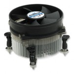
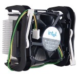
Si esta suelto y es como el de la foto tipo socket 775, con presionar hacia abajo y girar un cuarto de vuelta volveremos a dejarlo anclado, comprobar manualmente que los cuatro lados estan anclados. Si es del tipo Socket 478 lo normal es que uno de los cuatro brazos se rompa, porque salvo que inicialmente se monte erroneamente es muy dificil que se suelte, no es el caso del 775 que si lo es.
- Si al contrario tarda un rato en apagar el sistema y despues se apaga en cuanto intentamos encenderlo, casi seguro que la pasta termica que hace que el Microprocesador y el disipador de aluminio del ventilador tengan buen contacto para disipar el calor, se ha solidificado o incluso diluido por la temperatura. Seguir los siguientes pasos:
- La opcion sera quitar el Modulo Disipador – Ventilador de encima del Procesador, Mucho cuidado con el Socket 478, el Procesador de Pins si estiramos del ventilador saldra tambien y doblaremos irreversiblemente alguno de ellos, inutilizandolo.
- Limpiar de los restos que pudiese haber de masilla termica en el Microprocesador y en el disipador.
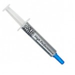
- Dibujar un par de circulos concentricos en el procesador de Masilla Termica, no hace falta poner demasiada, porque al poner el disipador luego lo que sobre nos desbordara por los lados y ensuciara el zocalo de procesador.
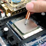
4. Volver a situar con mucho cuidado el Disipador-Ventilador, en el Socket 775 introduciremos primero las patas de plastico blanco, dentro de los agujeros de la placa base y despues daremos un cuarto de vuelta a los cuatro cierres. En el socket 478 pondremos inicialmente las 2 palancas una hacia arriba y la otra hacia abajo, fijandonos en la posicion que no ejerza presion, engancharemos los cuatro agarres y subiremos la 1ª palanca que teniamos hacia abajo y bajaremos la 2ª palanca que teniamos hacia arriba.
5. aprovecharemos para aspirar los ventiladores de la caja y Fuente de Alimentacion ya que estamos con las manos sucias
Posted in Hardware

